Designing Power Factor Correction Chokes
The power factor correction (PFC) choke is used in rectifiers with RC-load in order to provide the first harmonic of the AC input current with the power factor 1 . The frequency of the AC input voltage is normally 50 or 60 Hz. The switching frequency is use in a eide range between from 100/120Hz and 100 kHz.
There are 3 modulation types in use:
– FF => with constant switching frequency
– TM => with fixed-on-time and variable switching frequency
– FOT = with fixed-off-time
and 2 input current forms:
– COM =>continuous operation mode (small harmonics)
– DCM =>discontinuous operation mode
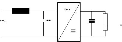
There are 2 basic schemas:
With the controller on the AC side

With the controller on the DC side

Here are the most important input parameters for design PFC choke, which has to be prescribed by power electronic designer.
– Imputative frequency f
– Switching frequency N*f
– Peak input current Im
– Inductance, linear up to Im
– All harmonics
– Ambient temperature
– Total losses
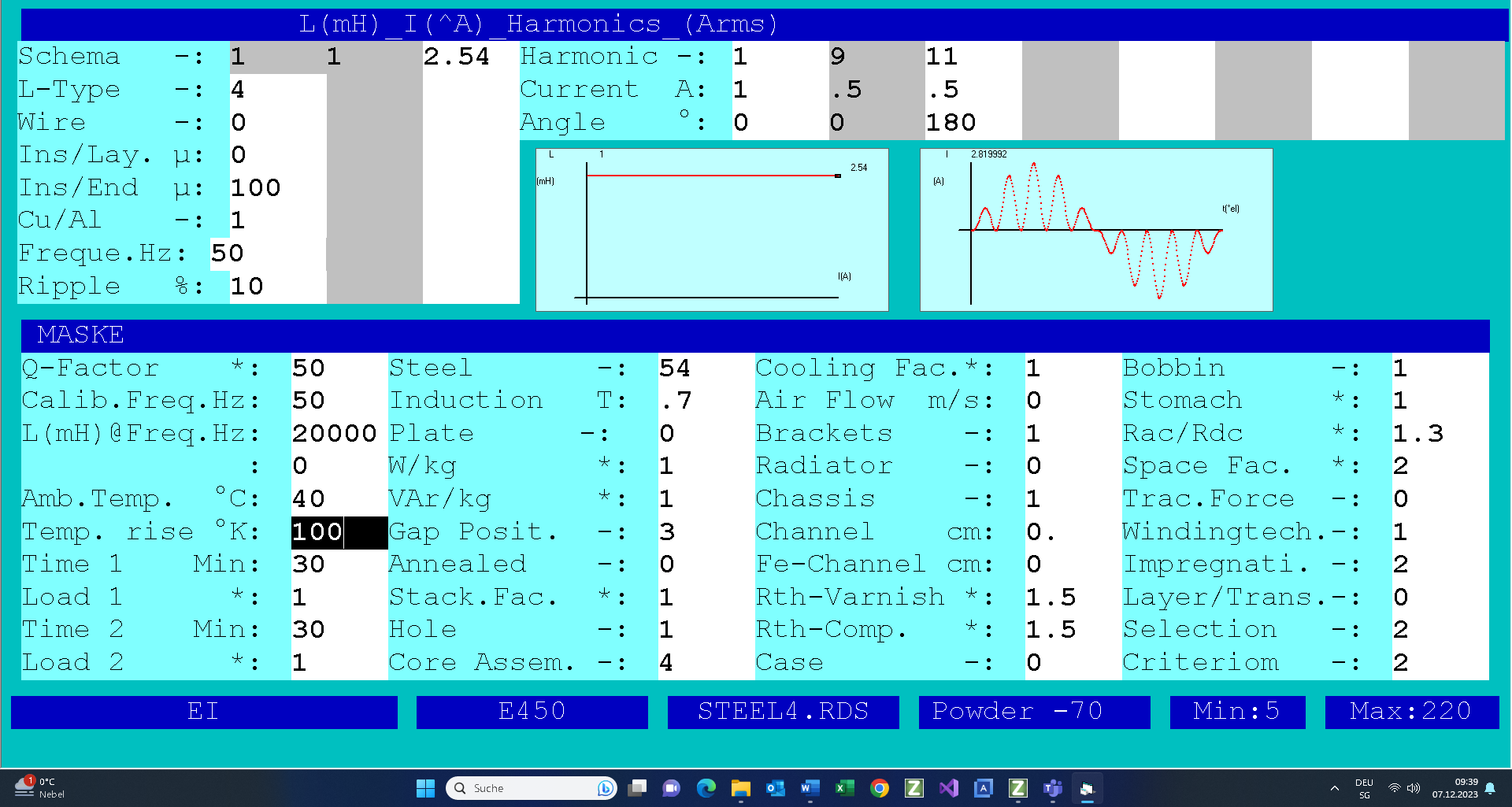
Typical input for design of DCM PFC choke
This modulation mode is used in low power range up to 100W with the switching frequency between 50 and 100kHz, using ferrite or powder cores.

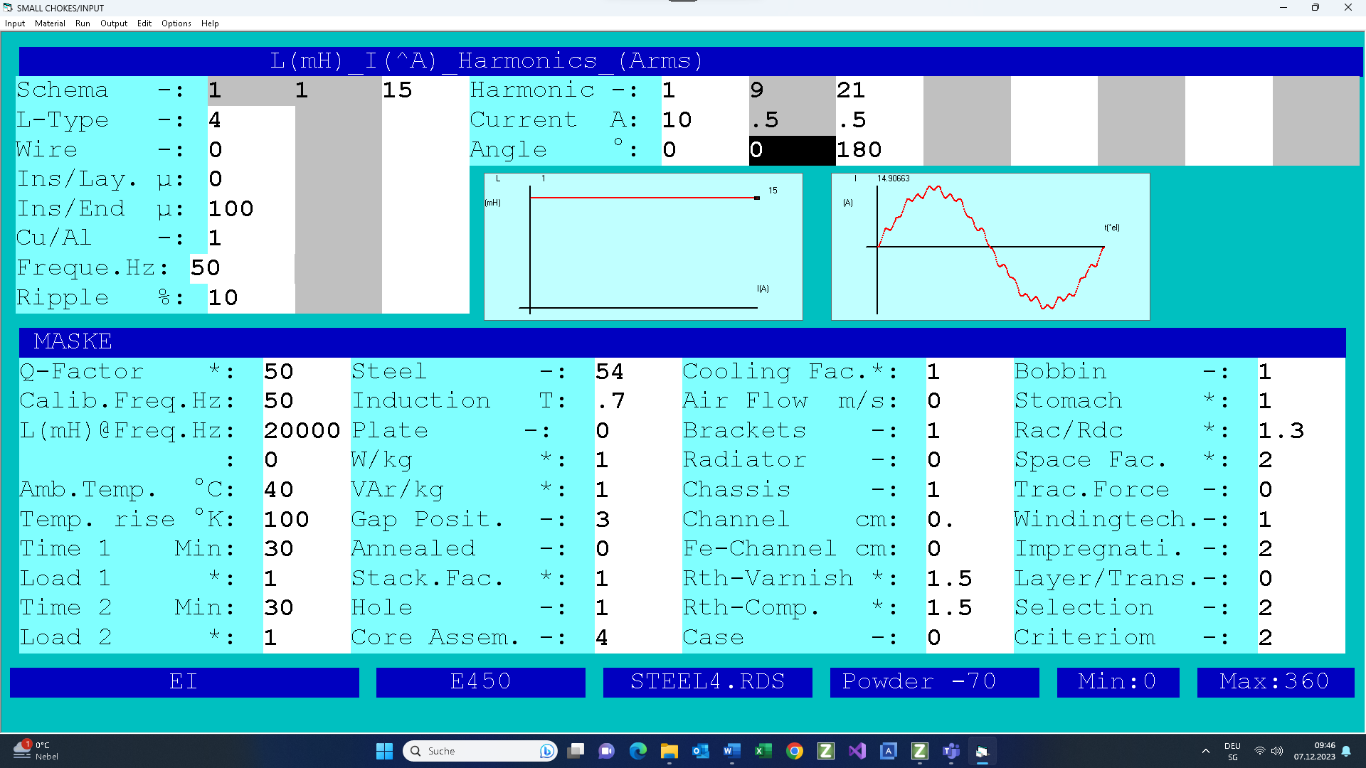
Typical input for design of COCM PFC choke
This modulation mode is used in power range up to over 1000W, with the switching frequency between 5 and 10kHz, using GO steel.

Note that the switching is very low (N=10) in order to get a good visible current diagram on the screen.