Designing a split core current transformer 1000A/0.1A, 10V, 50HZ
Get your input file here SCCT_1000A_100mA
INPUT:
A ”normal” current transformer has a very small magnetizing current.In a split core current transformer the primary current is the “magnetizing” current. In order to avoid the saturation of the core material, the core has to be gaped. Normally the induction B is in the linear area of the magnetizing diagram:
B = f(H)= Mi0*Wp*Ip^/Gap
Where: Mi0=12.56 10-7 in H/m
Wp – primary turns => n0rmally 1
Ipˆ– max. primary current in A
Gap – air gap in m
The next step is the secondary voltage Us and current Is. In this design example the output voltage Us=10Vand the output current Is 0.1Aand the load Rs=100 Ohm. Note that in a split core current transformer Wp*Ip>>Ws*Is
The next step is the setting of the inductive
voltage drop of the primary current Up. The core power Qp = Up*Ip. Note that the core size depends on the core power very much..
Wp=1
Ip=1000A
Up = 0.02V. Note that the primary input voltagr is for ca. 10% higher than the inductive voltage drop Up. In this design the regulation of the outoz voltage is 10%.
Qp=20VAr
Core cross section
Afe = Ip/4.44/f/B/Wp = ca 1cm2 = 10mmx10mm
Cpre window
D x H P 50mm x 50mm
Primary inductance
Lp=Up/Omega/Ip/Wp=0.02/314/1000 = ca. 0.06uH
Gap
Gap = Mio*W^2*Afe/Lp = ca. 2 x (0.8 ….9mm = 2 x35 mil
INPUT:
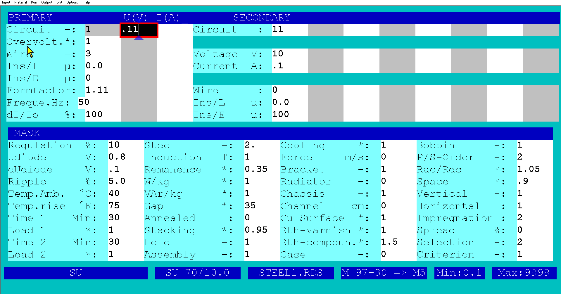
The primary has to have 1 turn and the input voltage has to be ca. 22mV. Due to the fact that the current version of the Small Transformers Program support the minimal input voltsge of 0.qV , the set input voltage ia 0.11V. The primary will be calculated with 5 turns. You have to change it in Test to 1 turn.
In order to limit the temperature influence on the output voltage the regulation is limited to max. 10% and Criterion =1..
Thr induction = 1T
Gap = 35mil = 35 x umm = 0.875mm per one gap.
PS-Order = 2 => The primary winding is wound over the secondary winding
The created core is 2 lecs, C-core with 2 gaps.
The core cross section 10 x 10mm with the wcore window 50 x 50mm for the 1000A cable.

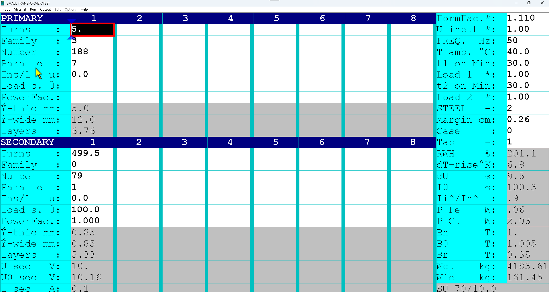
Here is the result in the test:
Input voltage factor r = 1.00 => 0.11V
Primary turns = 5
Secondary turns 499.5
Change Input voltage to 0.2 y 0.11 = 0.22V2 and press F6.
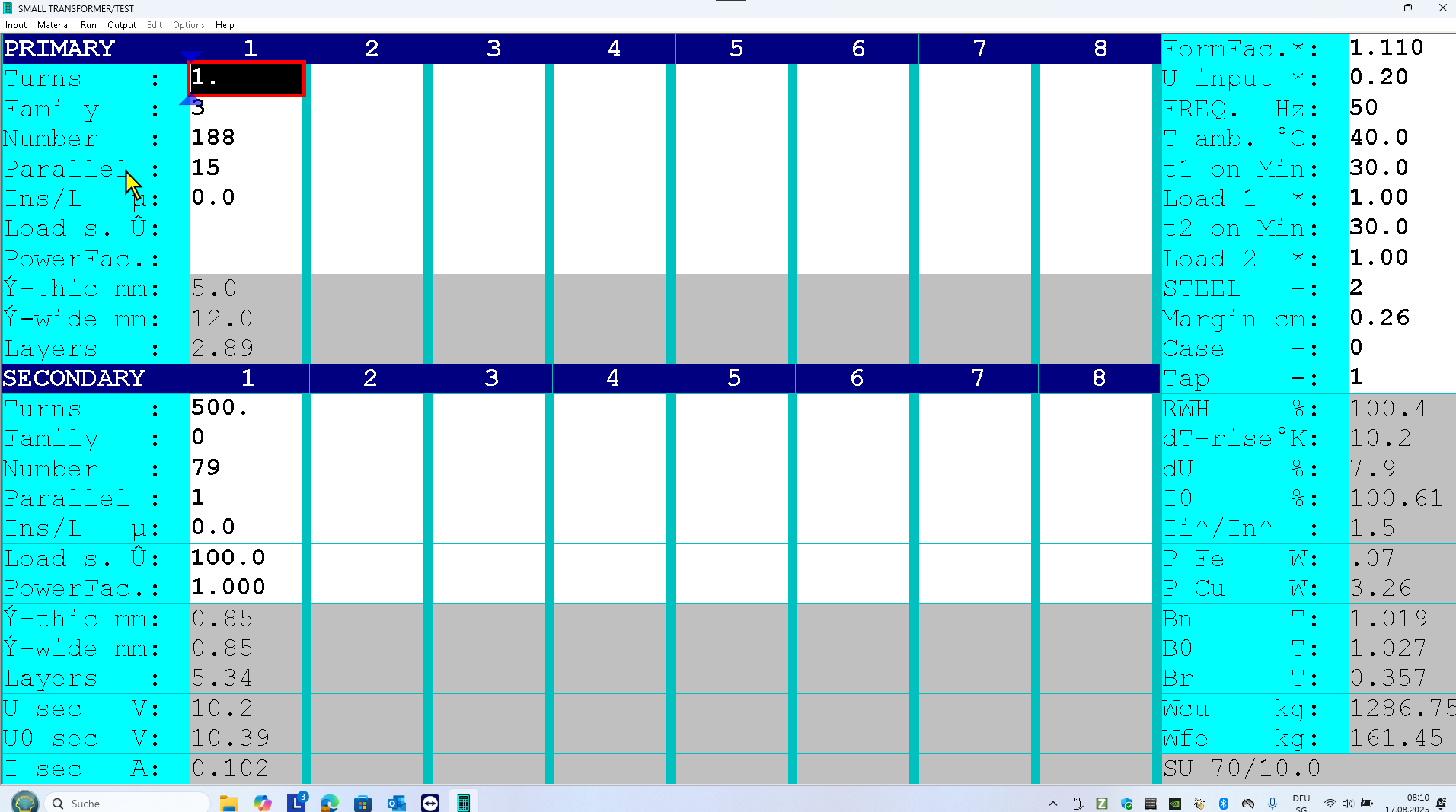
Now change the primary turns to 1 and the secondary turns to 500.
Press F6. Check the input current and the output voltage. Change the input voltage to vary the input current and the output voltage.

Here is the ONE turn solution created by varying the Input voltage and the gap in the input screen (in this design the gap was not changed).

Open the file SCCT: SCCT_1000A_100mA to read all result of this design.
CALIBRATION:
Set the primary current to 1000A. It has to be impressed and constant.
Vary the gap size in order to get the output voltage of 10 V.
The optimal accuracy (<1%) can be obtained by gap = 35.3mil.