
Get the RALE_INPUT-FILE for this design here.
TWO DESIGNS EXPLAINED:
Designing a 1600kVA,Yyn, 50Hz Distribution Transformer
Input :3x35kV+-10%,85kV_50Hz_1min,BIL 120kV, Cu discs –
Output: 3x690V,1340A,Cu foil 4×100//4×100 with oil tank
plus an additional design at the bottom of this page for which just the output file is shown
Designing a 1600kVA,Yyn, 50Hz Distribution Transformer
Input :3x35kV+-10%,85kV_50Hz_1min,BIL 120kV, Cu multi-layer, 8 sections with 7 layers –
Output: 3x690V,1340A,Cu foil 4×100//4×100 with oil tank
I. Designing a 1600kVA,Yyn, 50Hz Distribution Transformer
Input :3x35kV+-10%,85kV_50Hz_1min,BIL 120kV, Cu discs –
Output: 3x690V,1340A,Cu foil 4×100//4×100 with oil tank
General Information: Technical Parameters
Creating the Input4 input screens are used to set the input parameters for designing a transformer: · Winding parameters per limb · Core · Environment · Other and 3 screens for selection and set up of material : · wires · steels · cores. Criteria and Parameters of Design
The design of a distribution transformer is always framed by 5 criteria which have to be put into effect simultaneously:
Under this condition the first step is optimizing the core size to match the above mentioned prescribed design criteria for the optimal material price using some additional parameters such as: Transformer cooling media is oiltank. The cooling procedure is ONAN. 4 secondary windinsgs are inside. The setting of the voltages and currents is normally no problem.
Windings parameters per leg
SecondaryThe secondary is created in star connection. The sine wave output voltage is 400V. It has 4 windings. Each winding has 2 sections. 4 top and 4 bottom sections are wound at the same time in series and then parallel connected: 4x100V//4x100V. The rms output current is 1336 Arms. There are no current harmonics and there is no duty cycle operation mode. The secondary windings will be manufactured with Cu-foil with the vertical cooling channels of 6mm and 15mm (due to bar welded connector). The foil turns are insulated with 0.2mm insulation. The margin to yoke is 50mm:25mm less than the primary winding in order to suppress the eddy current losses in the foil winding! PrimaryThe primary is created in star connection. The sine wave input voltage is 20230V. There are no voltage harmonics and there is no duty cycle operation mode. The primary will be manufactured with Cu-flat wire with 44 discs winding technology with the horizontal cooling channels of h=6.5mm. The advantage of the disc windings is low voltage per turn(BIL test) and without any partial discharging problems. In order to suppress the high BIL pulse voltage the wire is insulated with 0.15mm (0.3mm between 2 wires in a disc). Now you see the input screen: |
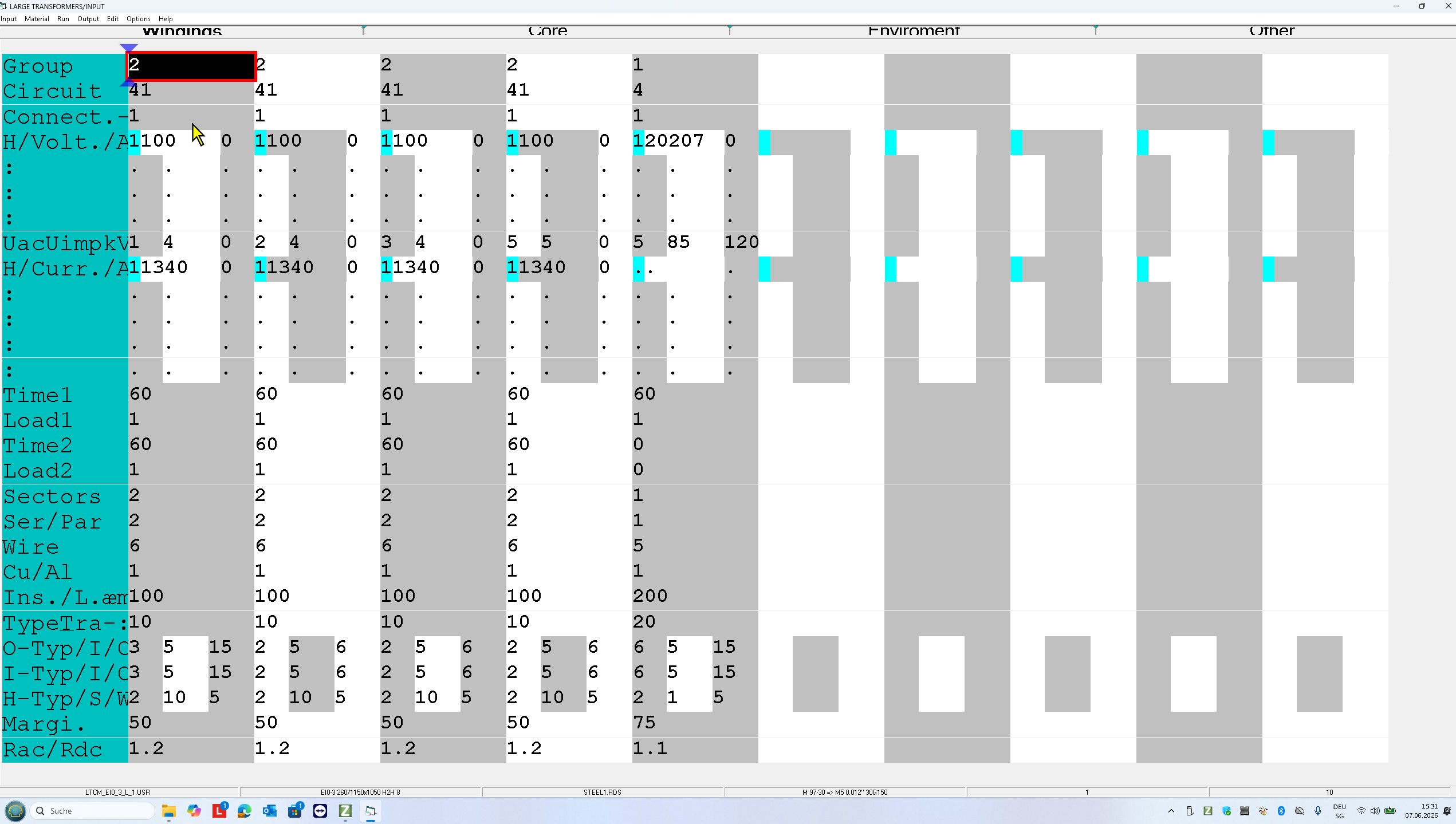
In this input screen are set the following parameters of all windings:
-The order
-The circuits and connections I,D,Y,Z,Dext …
-Nominsl voltages and currents with harmonics
-50Hz, 1 min test voltages and BIL impulse test voltages
-Cu and AL conductor type: wi round wires, rectangular wires and foil
-Spacing: If you double click the input fields O-Type/I/C or/and Margin, the program will automatically , according to the teest voltages, recommend you the size of the gaps and the insulations.
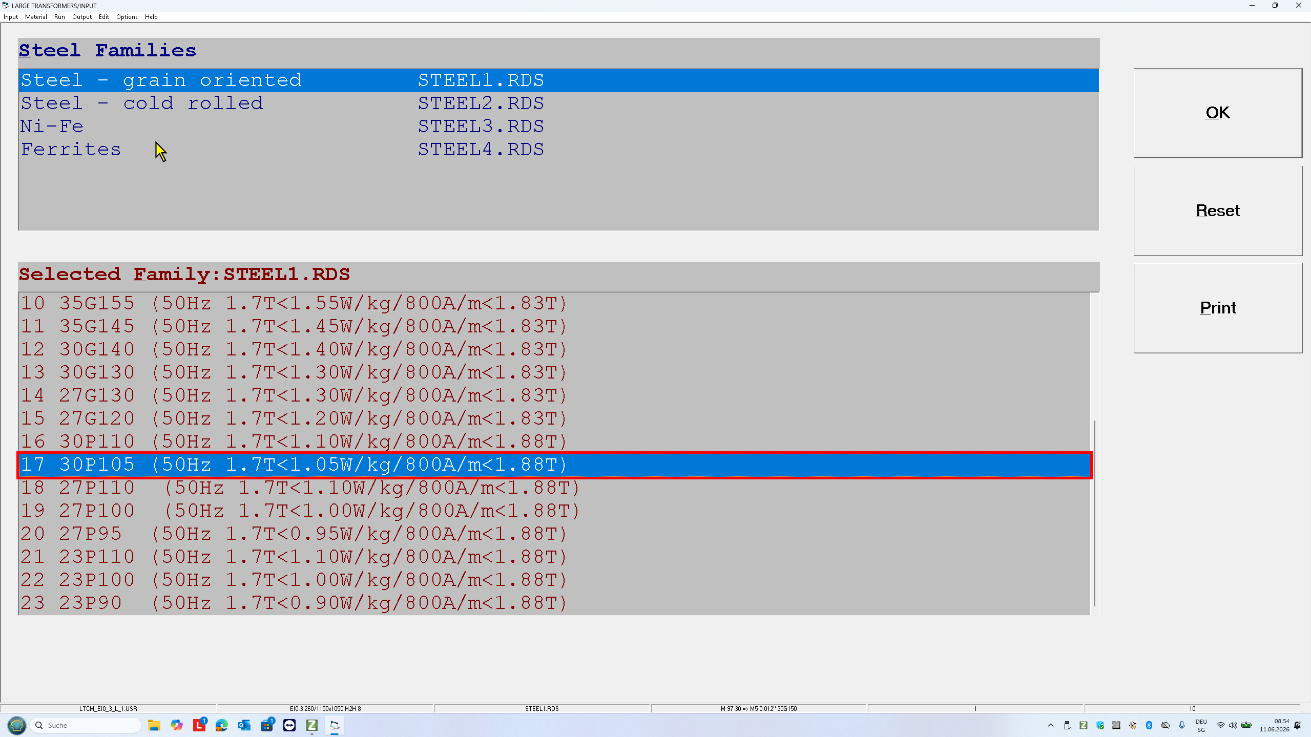
Press F11 to open the following screen. On this input screen you can select the steel.
Core and Steels
After the steel selection open the screen Core. On this input screen you can select the core assembly and set the frequency and induction at the nominal operating voltage:
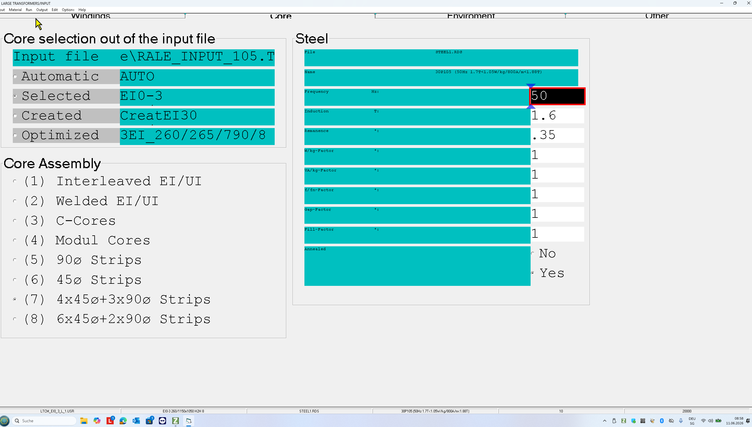
- The selected steel is M5 = 30P105, 030mm, 1.05W/kg at 1-7T,50Hz
- set the operating induction (1.6T) and the frequency (50Hz)
- select the core assembly 7 (45°&90°)
Environment
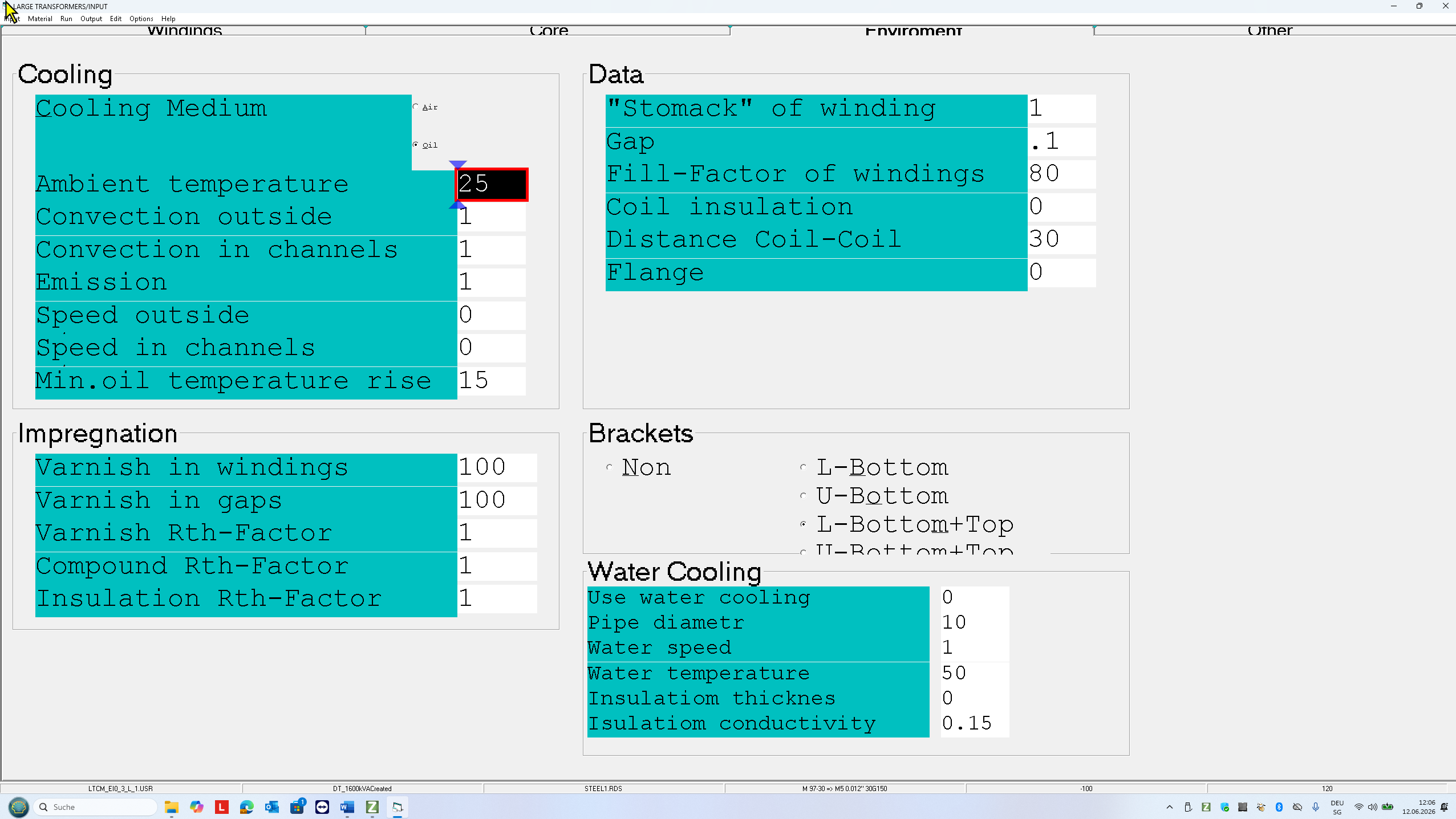
The cooling medium is oil with the average temperature 55°C.
The cooling surface of the core is increased by using 4 L-brackets on the core.
The minimum distance between the primary windings of 2 phases is 30mm.
There is no flange but both windings have to be fixed in order to suppress the axial forces during the short circuit operation mode.
There is no air in the transformer and in the oil tank!
In order to get an optimal oil tank size, set (if possible) the min. oil temperature rise so high that the average oil temperature lies between 65°C and 75°C.
Other Design criteria
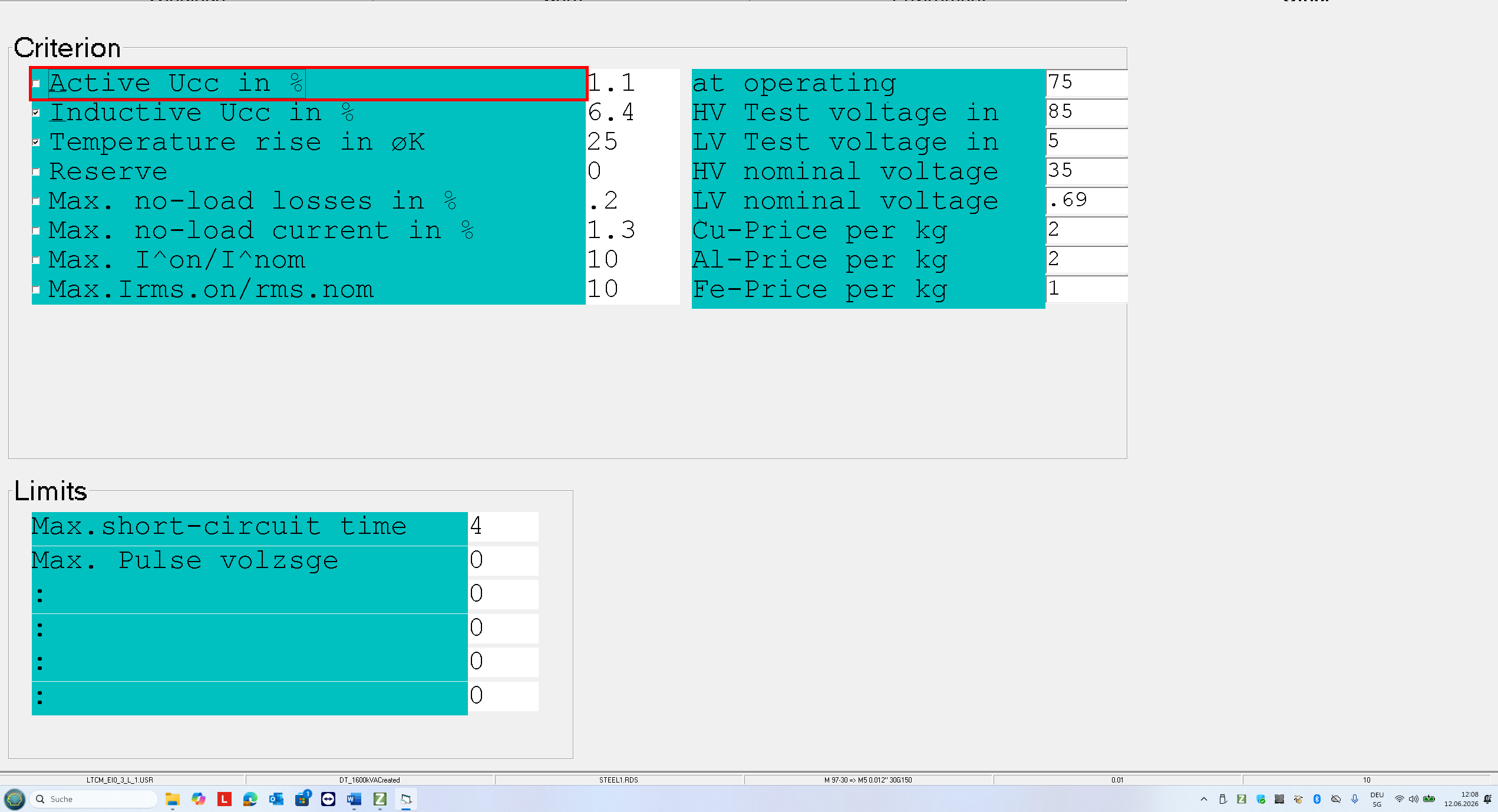
The selected criteria of the design and core optimization are:
– the winding losses (18000W => Active Ucca <= 1.125%) at 75 °C and
– the inductive short-circuit voltage Uccx= 6.4%.
If you prescribe also the temperature rise, then the program has to use the criterion which is more critical: either the winding losses or the temperature rise with the prescribed short circuit voltage.
The core losses and the no-load input current can be modified only with steel quality, core assembly and induction.
Core optimization
After you have set all input screens press F9. Now you need to select a core family and a sny core as template:
-3 phase core in the family with “round” leg cross section ( LTCM_EI0_3.L.1.USR) with 8 steps .
Click Core and then Optimize.
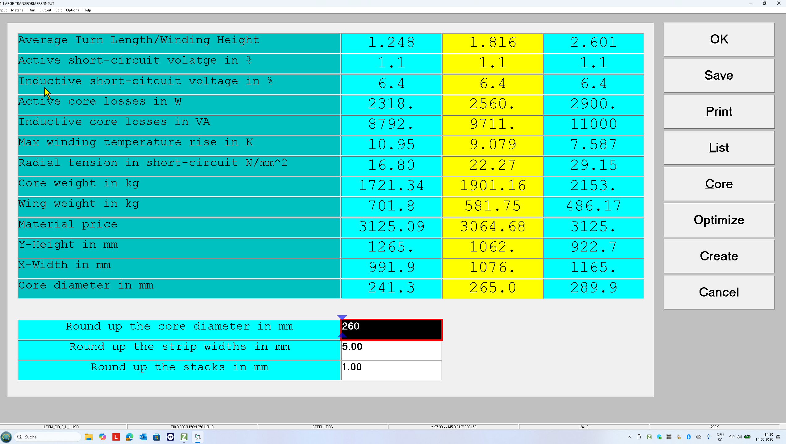
In this design the recommended core diameter is 260mm.
Read the transformer properties with the optimized core,
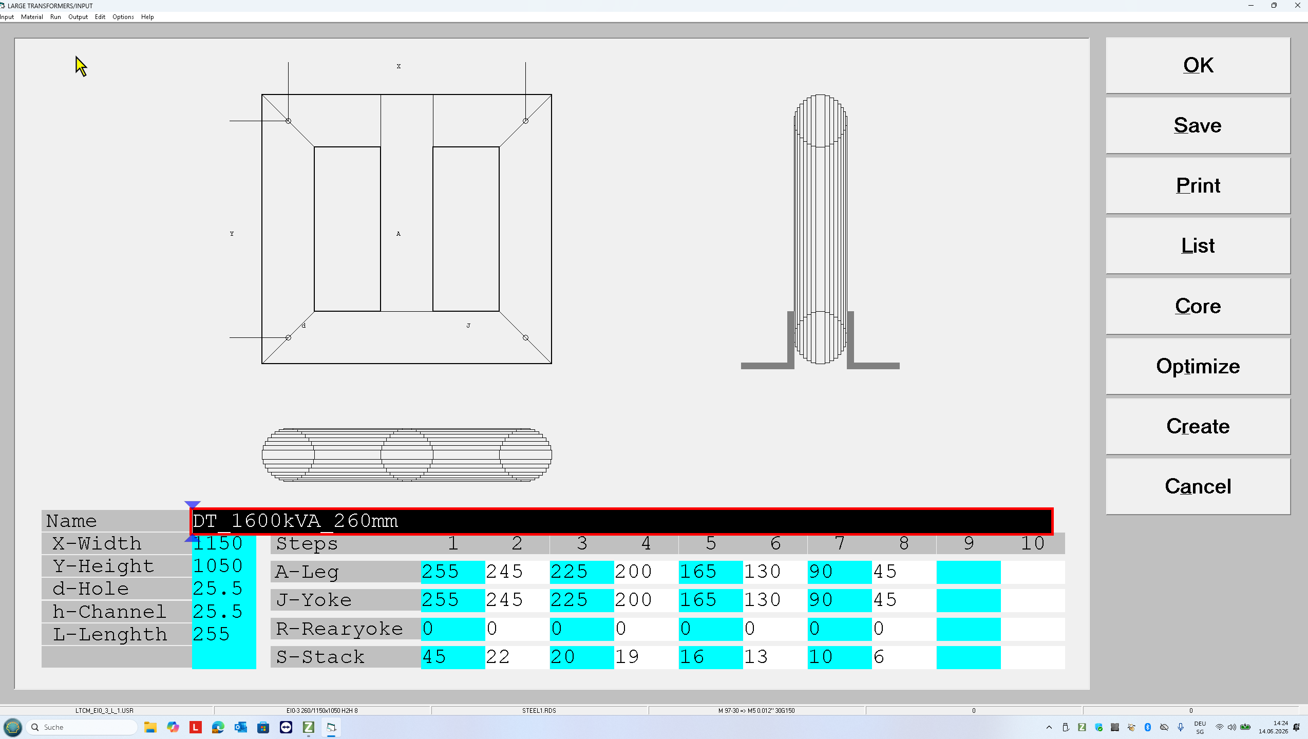
click Create and set.
-Core name DT_1600kVA_260mm
-X-Width=1150mm
-Y-Height = 1050mm
Click OK or SAVE to close the optimizing procedure.
Press F4 ti run design with the optimized core.
Click OK or SAVE to close the optimizing procedure.
Press F4 to run design with the optimized core.
OUTPUT
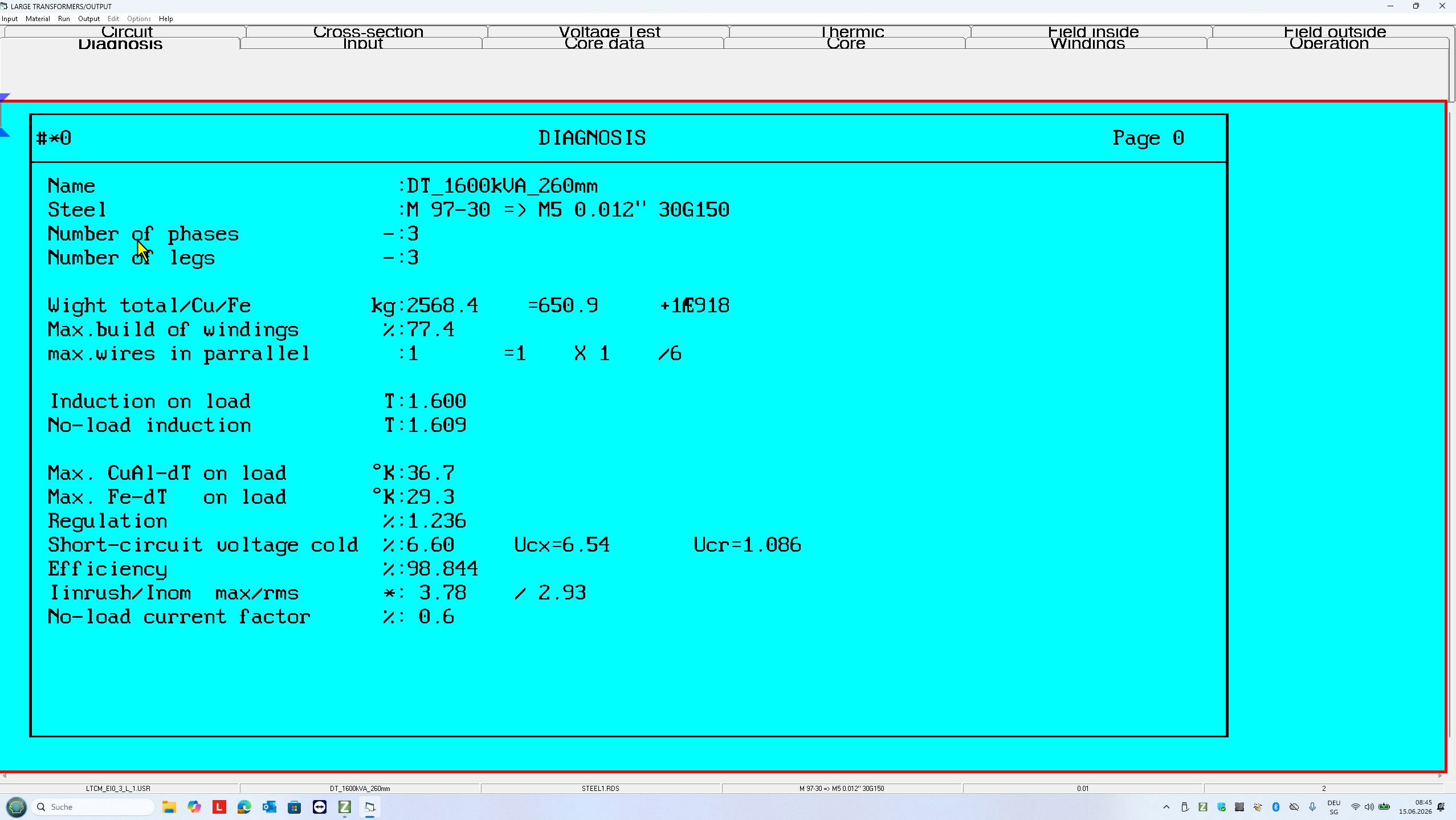
In the output screen you can view, print and save all results of the design.
If you would like to modify BY HAND some calculated parameters of the transformer, press F8 to print all results and then press F5 to open the test mode of design.
Test Mode
In the test mode you can modify by hand the following transformer parameters and press F6 to redesign:
-
Turns
-
Wire and foil size
-
Material (Cu or Al)
-
Number parallel connected wires and their order in strand
-
Cooling channels and insulations
-
Margin
-
Steel
-
Technology parameter (impregnation, gaps,…)
and set it under an operation mode changing:
-
Input voltage
-
Frequency
-
Loads and their K-factors
-
Duty cycle of each winding
-
Ambient temperature
-
Air flow
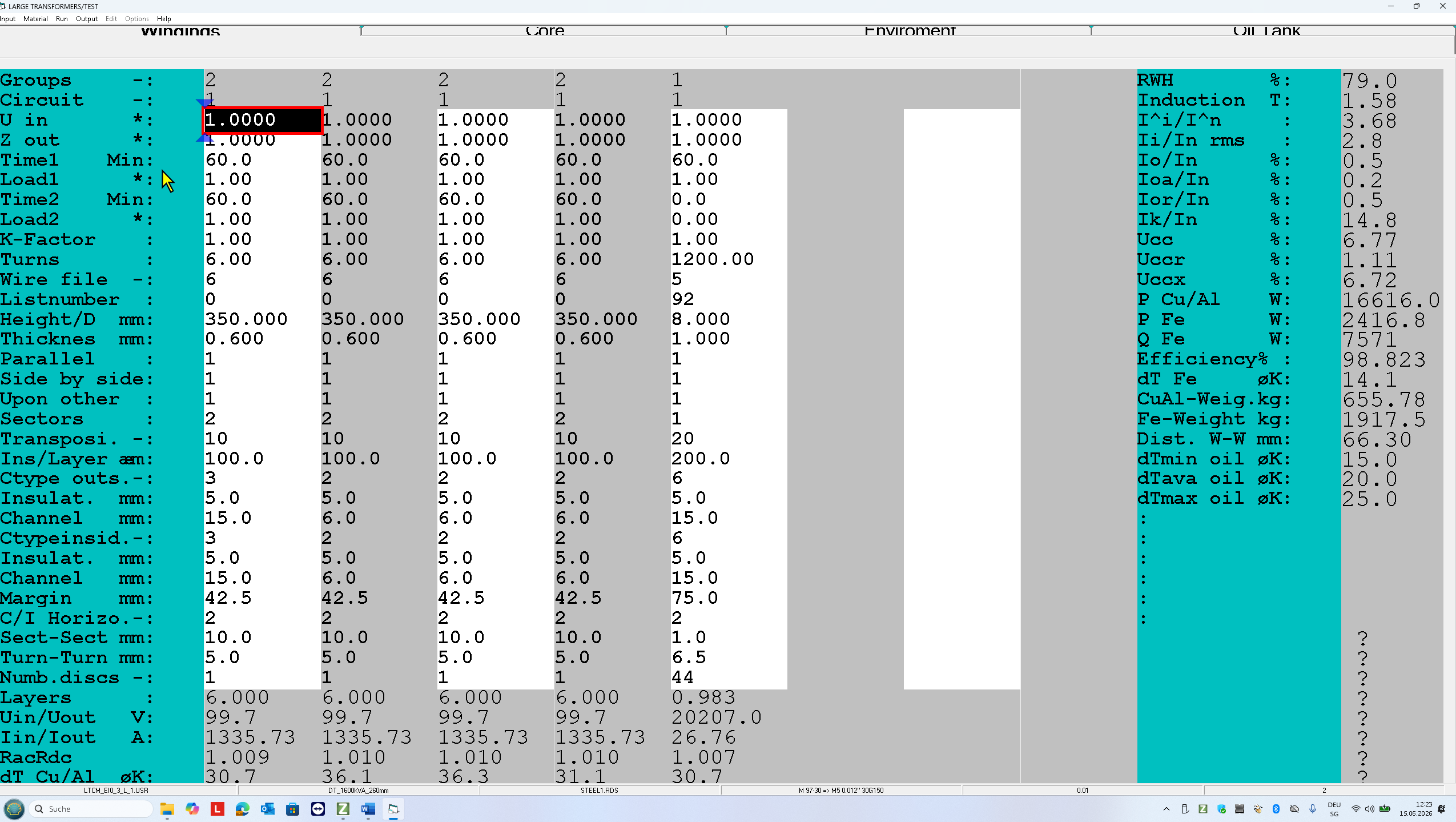
Now you can check the prescribed design criterion
-Ucc = 6.77% (7%)
-Pcu= 16616W (18000)
-Pfe = 2400W /3200)
-Temperature rise : 36 °K
– No load current: = 0.5% (/1.3%)
In the next step is the modification of the transformer in order to support the voltage regulation +-10%
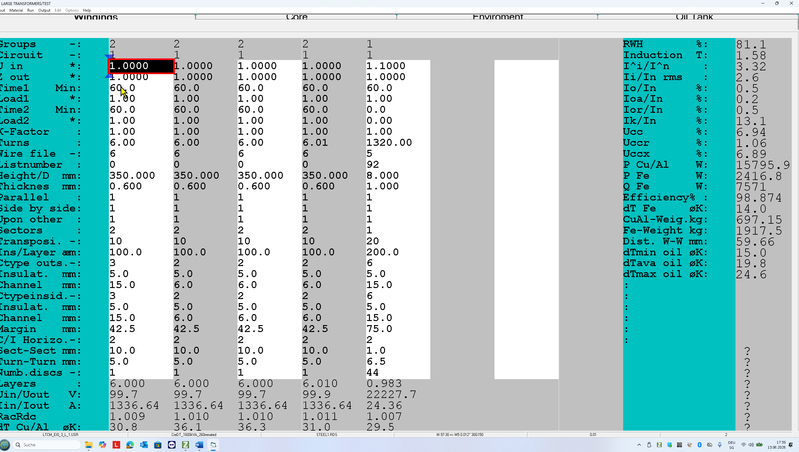
In this case the transformer is running under +10% overvoltage
-Uin =1.1
-Number of discs = 44 (Discs 36 to 44 are taps for voltage regulation +-4×2.5%)
-Set the primary turns 10% higher:1320 turns
-Set the secondary turns to 6 instead 5.98
-Foil thickness 0.6mm instesd 0.58mm
Now press F6 and then F8 to print the design results (5 A4 pages).
Output (5 printed pages and their content)
Finally here are 5 printed pages showing the design results: Click here to get the Output-PDF.
Here is what the pages show:
Page 1: Summary of the input parameters
Page 2: Core
Page 3: Windings
On this output pages you can check the windungs parameter
- 8 secondary wzndings ( 2×4 in series and parallel) 6 turnd Cu foil 350mmx0.6mm indulsted with 0.2mm
- Primary with 44 discs, 30 turns per disc, Cu 8x1mm, one side unsulation 0.15mm. 6.5mm between the discs
Page 4: Nominal operating mode
On this output pages you can check the prescribed parameter:
- short voltage:6-.77.09% (instead of 7%)
- core losses:2482W < 3200W
- No-load current: 0.5% < 1.3%
- Max temperature rise :36.7 °K
- radial tension in short-circuit: 7.61 < 60 N/mm^2
- Max temp. rises during 4s in short-circuit:77°K
Page 5: Electric fields at the the test voltages and BIL
On this output pages you can check the electric fields on the test voltages and theim pulse voltage distribution:
- The first secondary winding has the spacing insulation-gap(/i):_5mm-15mm. The test voltage is 4kV. The electrical fields on the test voltage 4kV are Ei=1.6kV/mm and Ed=0.3kV/mmNote that the break down Ebd, partial discharge Epd and creeping break down Ecb are much bigger.
- The spacing between the last secondary winding and the primary winding in gap-insulation-gap (gig) : 15mm-5mm-25mm. The electric fields on the test voltage 85kV are Eg=2.9kV/mm and Wi=1.3kV/mm
- BIL: the impulse voltage is 120kV. The primary is in star connection. The star is grounded. The distribution factor is 9.2 and the max. voltage between 2 primary turns is 838Vwith primary wire insulation of 0.06mm. f you would use the wire insulation 0.15mm then the max. voltage between the primary turns would be 1500V.
Oil tank Design
In this oil tank design the average oil temperature rise could be 43°K instead 33°K. If you would like to use this oil tank you need to redesign this transformer with min. oil temperature rise 25°K instead 15°K or you increase the cooling ribs on the oil tank.
Here comes a second design as announced above:
II. Designing a 1600kVA,Yyn, 50Hz Distribution Transformer
Input :3x35kV+-10%,85kV_50Hz_1min,BIL 120kV, Cu multi layer,8 sections with 7 layers
Output: 3x690V,1340A,Cu foil 4×100//4×100
with oil tank
Design procedure analogously as described above.
Therefore, you get here only the OUTPUT-PDF.