Designing the 24 pulse rectifier 4 x 600Vdc/1000Adc with 2 dry Dext/YD transformers, driven by 3 x 6000V, 50Hz (Get your input file here)
A 24 pulse rectifier has 4, with smoothing chokes , parallel connected 6 pulse bridge rectifiers.. Normally it is driven by one 3 phase transformer in connection D/-ZYZD or Y/-ZYZD with the following properties:
- 4 phase secondary voltages are equal
- The phase angles of 4 secondary phase voltages to the primary phase voltage are -15°,0°,15°,30°.
- 4 commutating short circuit currents in the primary winding have to be equal by using 4 three phase chokes between the secondaries and the rectifiers. In order to avoid using the commutating chokes there are versions with 4 parallel connected transformers ( D(Y)/-Z),D(Y)/Y, D(Y)/Z,D(Y)/D) or with 2 parallel connected transformer Dext(Z)/YD and -Dext(-Z)/YD
The most important function of a 24 pulse rectifier is to remove 5.,7.,11.,13.,17.,19., 23. and 25. current harmonics out of input current.
In this design example the 24 pulse rectifier is driven by 2 parallel connected transformers.Both transformers have the windings connection D/Dext/Y. The first secondary D is wound inside. The second secondary Y is wound outside. With this order of the windings the calibration of the secondary commutating currents is optimal. Note that the short circuit currents can be too high. The phase angle of the secondary phase voltages are shifted +7.5° (T1) and -7.5°(T2).
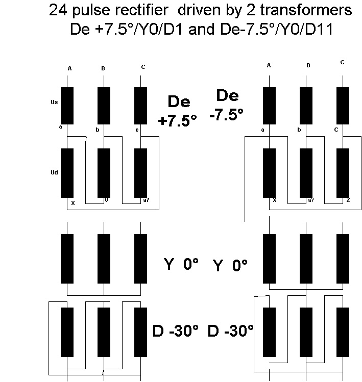
The 24 pulse rectifier with 2 transformers is created by two 12 pulse rectifier. 5.and 7. current harmonics do not exist in the primary windings. 11.,13.,17.,19.,23, and 25. current harmonics exist in the primary windings but they are very small in the net input current:0 to 5% of the nominal net input current.
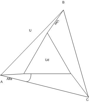
Delta extended vector diagram
U= 6000V
Alfa = 7.5°
Ud = 2*U*sin(30-Alfa)=4600V
Uex= 2*U*sin(Alfa)/1.73 = 910V
Design parameters
|
Designing a 3 phase, 50Hz, 24 pulse rectifier with 2 D/Dext/Y transformers |
UD = 470V |
|
4 x 6 pulse rectifier output dc voltage and dc current |
Udc=600Vdc Idc = 1000Adc |
|
Test voltage 1min, 50Hz BIL |
16kVrms 30kV |
|
Frequency |
50Hz |
|
Cooling Ambient temperature |
AN |
|
Temperature rise |
Max. 115°K, insulation class F |
|
°Short-circuit voltage |
Ucc = > 5% |
|
Steel & Core |
M6, annealed, strips for alternated stacking (45°&90°), |
Creating Input
4 input screens are used to set the input parameters for the designing of a transformer:
- Winding parameters per leg
- Core & Steels
- Environment
- Criterium of design
and 3 screens for selection and set up of material .
- wires Al,Cu (round, rectangular, foil)
- steels
- cores.
Windings parameters per leg
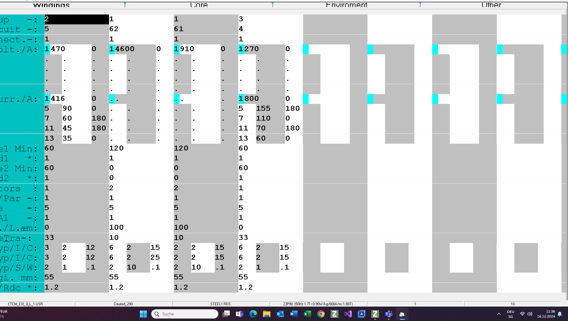
Primary
The Dext primary is created with 2 in series connected windings between 2 secondary windings. The sine wave input voltages are Ud= 460V and Uex = 910V per winding to shift the secondary phase voltage for 7.5°. The primary windings will be manufactured in 2 sections with Cu rectangular wire. With this windings order the commutation current of the inside secondary does not depend on the outside secondary and the eddy current losses in the primary are smaller.
Secondary
Both secondary windings are wpomd with rectangular wire strands 2 x Y (Y=2 to8) with transposition.
Core assembly & Steel parameters
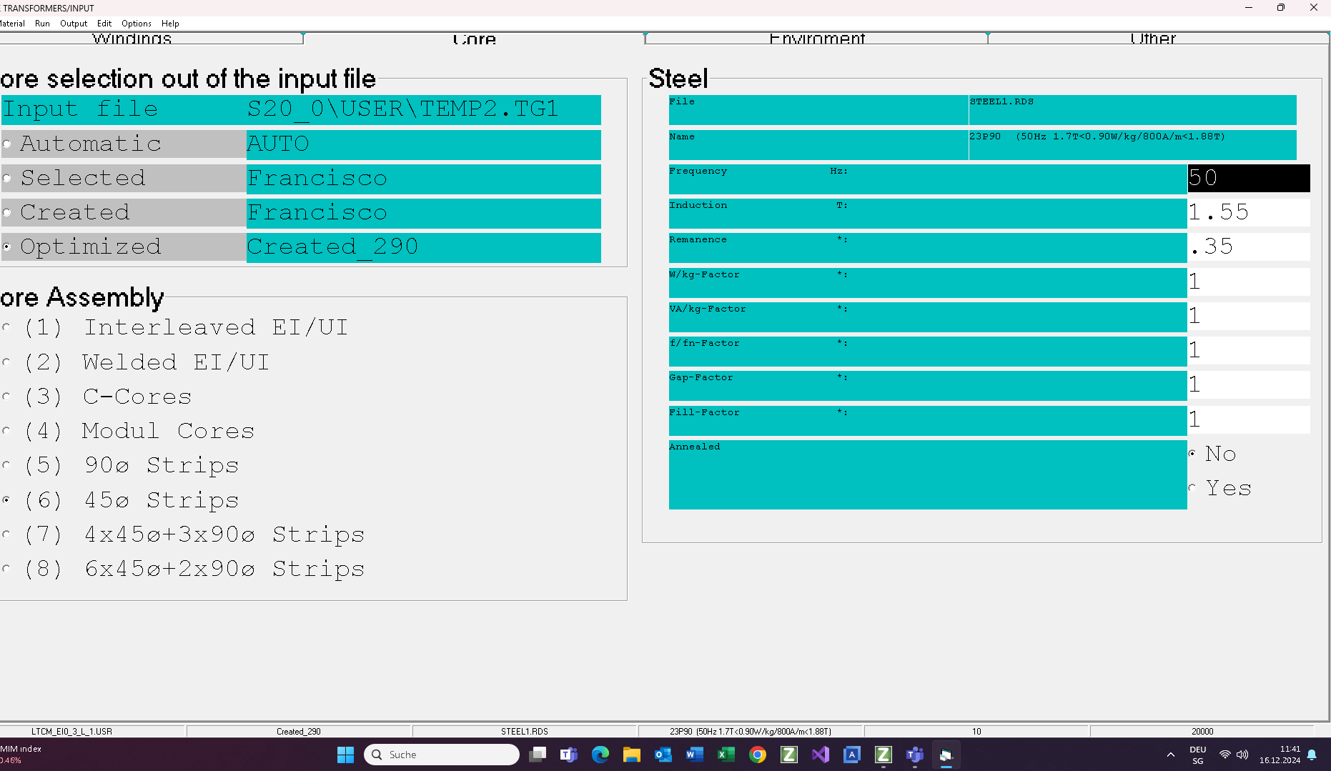
The most important information on this screen are:
- Core name and irs assembly
- Steel nam GO e 23P90
- Frequency 50Hz
- Induction 1.55T
Ambient parameters
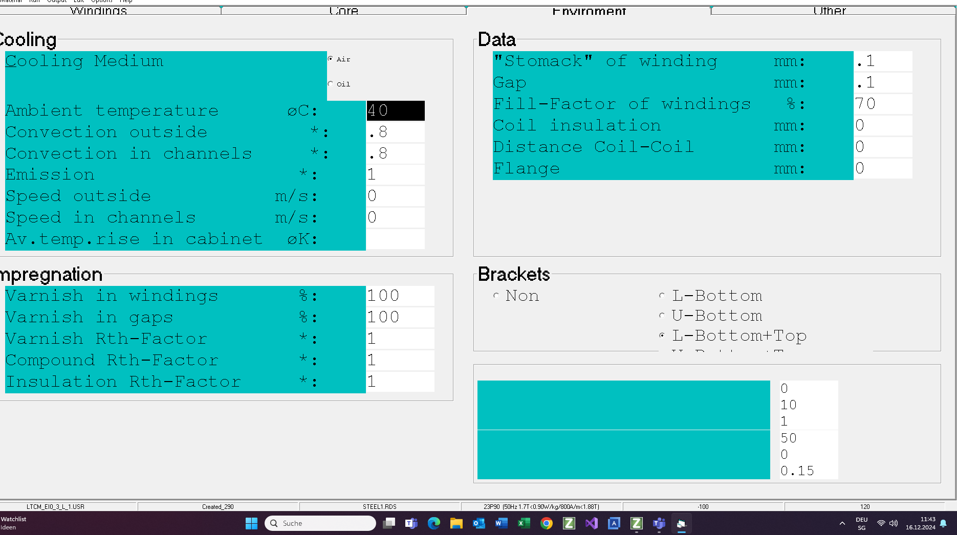
Cooling media : AN
Ambient temperature: 40°C
Impregnation : Vacuum, 2 componentes varnish
Criterium
Load losses = 1.2%
Temperature rise = 115°K
Test Mode
If you are not satisfied with the solution made by the program you can switch into the Test Mode and change your transformer by hand:
- Turns
- Wire size
- Material (Cu or Al)
- Number parallel connected wires and their order in strand
- Cooling channels and insulations
- Margin
- Steel
- Technology parameter (impregnation, gaps,…)
and then you can set it under an operation mode changing:
-
- Input voltage
- Frequency
- Loads and their K-factors
- Duty cycle of each winding
- Ambient temperature
- Air flow
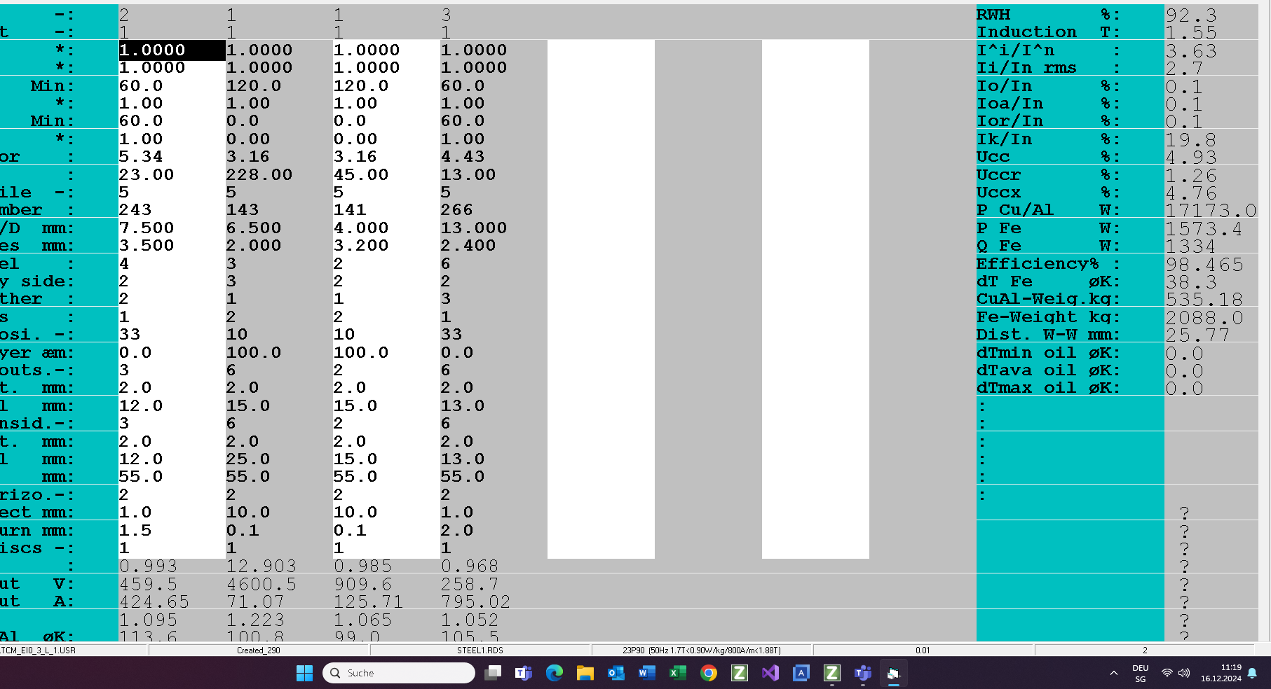
Commutation operation mode
During a commutation one secondary winding works in short circuit operation mode. All other secondary windings are in no-load operation mode. If tall primary commutation currents are equal, then the distribution currents of the parallel connected rectifier is optimal and the size of the harmonic currents in the net input current minimal.
Commutation of the inside secondary:
1. Input voltage = 0.05 x Unom
2. Space between the secondary winding = 32mm
3. Outside secondary in no-load operation mode
4. Id=52A, Iex=94A
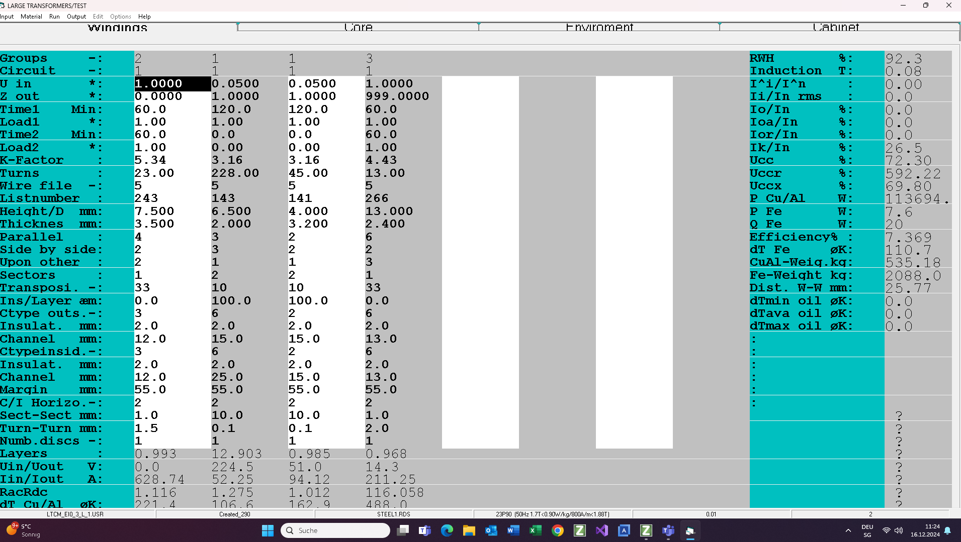
Commutation of the outside secondary:
1. Input voltage = 0.05 x Unom
2. Space between the outside secondary winding = 32mm (calibrated by hand)
3. Innside secondary in no-load operation mode
4. Id=52A, Iex=94A (very good result)
Output
Finally you get the results (4 pages; PDF).