CLICK TO GET INPUT FILE: RaleInput_006
How should one design a three-phase rectifier/safety transformer for 24Vdc, 80Adc with RC load,
as per IEC 38 and IEC 61558 ?
Technical specification relevant only for design
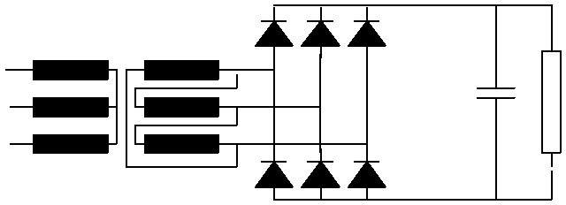
Electrical data and schema
| Input voltage | 3 x 400V, +10%, -10%, sinusoidal |
| Frequency | 50Hz |
| Min. output voltage | 20.4Vdc, at -10% input voltage |
| Nominal output voltage | 24Vdc, at nominal input voltage |
| No-load voltage | 28.8Vdc, at +6% input voltage |
| Nominal output current | 80Adc, RC load |
| Voltage ripple | max 5% |
Ambient and operating conditions:
| Ambient temperature | 40°C |
| Mode of operation | Continuous operation |
| Test conditions |
Non-inherently short-circuit proof,
|

Design criteria
Insulation class B
Normally, we try to provide effective protection both for the transformer and for the rectifier. Very often, we arrive at a combined protection solution consisting of three fuses matched to the rectifier and a thermal fuse. For these reasons, short-circuit and overload are not design criteria. The design criterion for purposes of IEC61558 is only temperature T nominal = 120°C
Max. winding temperature in nominal operating mode = 120°C
Max. winding temperature in test mode is limited by thermal fuse at 125-130°C.
The above-prescribed limit values for voltages and for the ripple of a 24V dc supply are laid down by IEC 38. A rectifier/transformer with RC load, for which the minimum and maximum output voltages are prescribed, is designed with the criterion regulation of DC voltage (Criterion = 1, Regulation -10%).
Output voltage ripple
Ripple= 100*(Udcmax-Udcmin)/(Udcmax+Udcmin)
The program calculates the magnitude of the required capacity on the part of the smoothing condensers for the prescribed DC ripple.
5% ripple is prescribed in accordance with IEC 38
Bobbin
Our calculation was performed with a single section bobbin. .
Induction and Fe quality
The choice of induction is selected at a voltage below the input voltage of minus 10% between 1.2 and 1.4.
The rectifier/transformer is very often installed together with the rectifier in a case or in a cabinet. For that reason, the loss output of the transformer should be sized low and the grain-related Fe quality should be used: M6X, ORSI 111,…
Connection of transformer windings
The primary winding is connected in a star circuit. The secondary is used in “Delta”, so that the current through the winding is less and the application of parallel-connected flat wires can be avoided.
Procedure for design
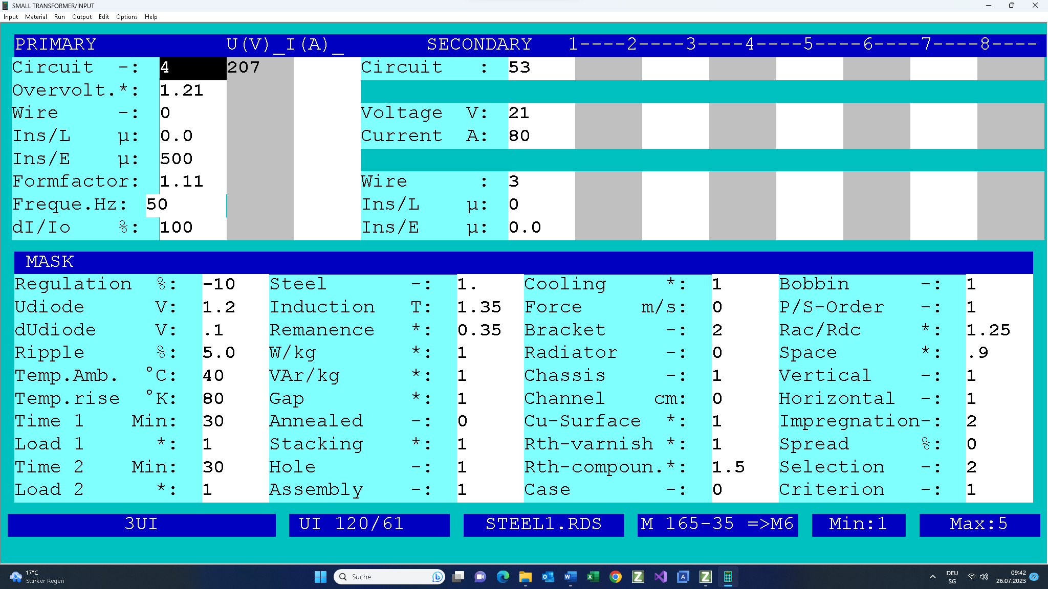
Fill in the design input mask as follows. If you need any help, press function key F1. There is extensive description for each input field.

The output voltage of 21Vdc at 80Adc is ensured at the min. input voltage of 207V e. The max. winding temperature is designed simultaneous with the max. input voltage of 253V < 110°C.
DC voltage Regulation = -10% was selected such that the maximum temperature of the windings does not exceed the value of 120°C =T nominal and the output voltage is within the limits prescribed by IEC 38.
Rac/Rdc = 1.25 was increased such that the program uses no parallel-connected flat wires.
Winding space = 0.9 should be used for automatic selection of the core (Selection=0) with thick wires.
The Selection input field is set at 0. This means that the program should search on-line for a suitable core for this application, from your selected 3 phase core family.
Start your design work. In the system for automatic selection of the core from your library.
On completion of the design work, the following design data will be available and can be downloaded as a PDF and printed (click on this link).
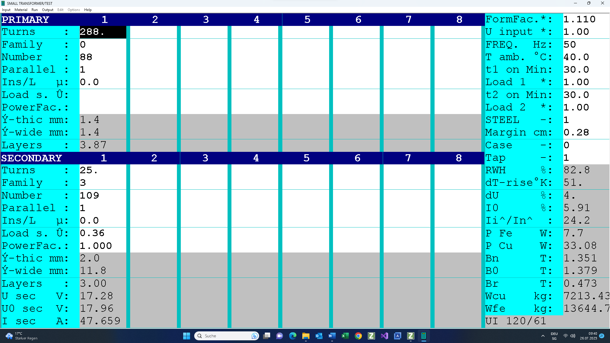
The next step is the calculation with the min. input voltage of 207V via the test input screen.

The results are shown in a PDF which you can download and print by using the following link.
This is followed by checking of the design data.
- Firstly, we check the DC output voltages in no-load mode for input voltage of 244.3Vac: 27.1Vdc < 28.8Vdc
- We then check the winding data and the filling factor (82.0<100%).
- The maximum temperature of the windings is 40°C+66.9°K = 106.9°C < 115°C.
This is followed by checking of the output voltage for an input voltage of 207V:
U in = 1.
If the design data is not satisfactory, then there are two ways by which we can implement the desired correction:
- You can return to the input mask (function key F2), correct the input data and redesign the transformer.
- Or you can access the test program (function key F5), modify the designed transformer manually and redesign the transformer by that means.
- On completion of the design work, you can print out the design data on-line, or save it on your local PC and print it out off-line. The output data file from this design example, CAL0006E.TK2, is supplied together with this document. Copy it into the directory in which your Rale demo program is installed.
Tips & Tricks
Temperature in nominal operating mode is too high
- Reduce your regulation and increase your induction.
- Employ a better iron quality.
- Increase your cooling surface area. In the case of 3UI cores, the base angles are very effective for this purpose. You can reduce the windings’ temperature rise by approximately 10%-15%.
Smoothing condenser
For the prescribed DC ripple of 5%, the program has calculated the value of 33000µF+-20%.
For the same output voltage ripple, a 2-chamber transformer requires only 6700µF!
Regulation
We selected regulation = 3.5%, so that the overtemperature would not be too high. In the case of a double-chamber transformer which has a higher scatter inductance, a higher degree of regulation is permissible. In our case, regulation = 5% is perfectly suitable.