How should one design an 8000VA transformer for medical premises in accordance with IEC 61558 ?
Technical specification relevant only to design
Electrical data and diagram
| Input voltages | 230Vac, sinusoidal |
| Frequency | 50Hz |
| Nominal output voltage | 230Vac |
| Nominal output current | 34.8A (8000VA) |
| Short-circuit voltage | 3% (cold, +-20%) |
| Inrush current factor | max 8 x I^nominal |
| No-load current | max 3% |
Ambient and operating conditions:
| Ambient temperature | 40°C |
| Mode of operation | Continuous operation |
| Test conditions | Non inherently short-circuit proof transformer, class B, overload protected by thermal fuse in the primary winding and short circuit protected by a fast fuse on the primary side. |

Criteria for design
A non inherently short-circuit proof transformer as per IEC 61558 is equipped with a safety. Very often, we arrive at a combined protection solution, which consists of a primary-side fuse and a thermal cut-out. For this reason, short-circuit and overload are not design criteria. The design criteria for purposes of IEC 61558 are temperature Tnominal, the maximum permitted short-circuit voltage of 3% and the inrush current, whose maximum level is eight times the peak value of the primary nominal current. Since IEC 61558 permits utilization of two condensers for compensation of the reactive no-load current, we should limit the active no-load current and core losses to approximately 2%, which is not usually a problem.
|
Insulation class |
A |
E |
B |
F |
H |
|
Max winding temperature in test T max (° C) |
200 |
215 |
225 |
240 |
260 |
|
Max winding temperature in nominal operation T nominal (° C) |
100 |
115 |
120 |
140 |
165 |
|
Short-circuit voltage (%) |
<3 |
<3 |
<3 |
<3 |
<3 |
|
Inrush current factor |
<8 |
<8 |
<8 |
<8 |
<8 |
|
No-load current (%) |
<3 |
<3 |
<3 |
<3 |
<3 |
Insulation class
- Max winding temperature in nominal operating mode = 120°C
- ax winding temperature in test mode = 225°C
(with the thermal fuse it is limited to 130°C)
Design criteria
Computer program employs two design criteria:
- Regulation <3%
- Temperature rise <80°K for 40°C ambient temperature and insulation class B.
Note that short-circuit voltage for a single-section bobbin is very closed to the regulation.
Since we do not know which of these criteria will be the more relevant to our design, we shall enter Criterion = 0 and leave it to the computer program to decide.
Bobbin and core.
Medical transformers have to be produced with a low internal resistance and with low leaking impedance. For this reason, transformers for medical purposes are constructed exclusively with single-section bobbin . For practical purposes, there is only one choice of UI core form to select for the 3kVA to 10kVA output power range.
Inrush current
The peak value of the inrush current, cold, in the first period after switch-on at the zero-axis crossing point, should not exceed a factor of 8 x the peak value for nominal input current. This can best be achieved if:
- The nominal induction is 1.1T-1.2T.
- The transformer is constructed with a defined gap distance of approx 0.05-0.10 mm, so as to reduce residual magnetism (remanence ).
- The primary winding is wound outside.
Induction and iron quality
Low irush-current transformers with a inrush factor of <8 are operated with a low induction (1.0T-1.2T). For this reason, we use virtually nothing but cold-rolled iron quality of 5.3W/kg at 1.5T, 50Hz.
Short-circuit voltage
The maximum permitted short-circuit voltage is 3%. In accordance with IEC 61558, a transformer’s short-circuit voltage is measured in the cold state at 20°C. The permitted tolerance is +-20%.
The computer program calculates short-circuit voltage. However, this cannot be used as a design criterion. We shall use regulation, since a single-chamber transformer’s regulation is practically identical to its short-circuit voltage.
In the design process, regulation of 3.3% to 3.6% is used, on account of the permitted short-circuit tolerance of +/-20%.
Cooling channels
By setting “+” in front of the voltage value the windings are provided by 4 cooling channels of 8mm in front and back: 2 between the secondary and the core and 2 between the secondary and the ptimsry.
Procedure for design
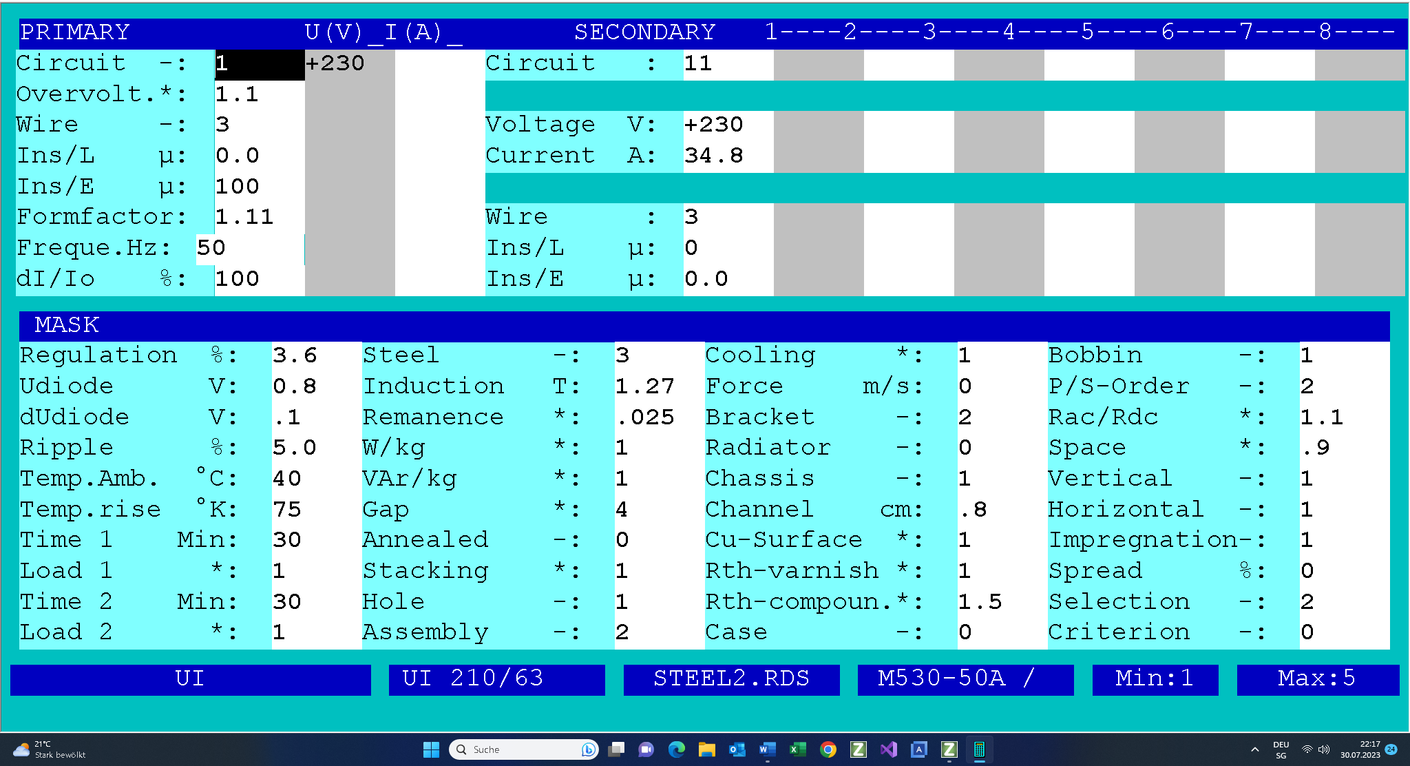
Fill in the design input mask as follows. If you need any help, press function key F1. There is extensive description for each input field.

The core UI210/63 is selected by hand .
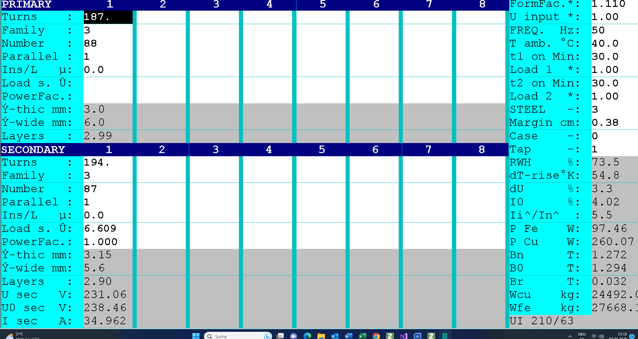
On completion of the design work, the following design data will be available and can be printed on three pages (click on the link to view PDF).
This is followed by checking of the design data.
- We now check the winding data and the filling factor (73%<100%).
- The maximum temperature of the windings is 40°C+64.9.0°K = 104.9°C < 120°C.
- Short-circuit voltage = 3.32%< 3.6% .
- The inrush current factor is somewhat less 6.9 7<8. We could use a higher induction.
- Max. core losses should not exceed approximately 2% of the nominal output (126W/8994VA=1.35% < 2%).
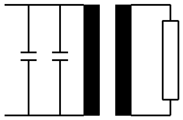
The reactive component of the no-load losses is 596Ar. It has to be compensate by parallel connected capacitors on the primary side :view the schema
This is followed by checking of the output voltage for a nominal input voltage of 230V: Uin = 1.

Once you are done, you can print the results (click on the following link).