CLICK HERE TO GET INPUT FILE: RaleInput_010
Designing a 100kHz, universal flyback transformer
for input voltage 125-700Vdc and output power 200W
The Operating Modes of a Flyback Transformer
The following flyback transformer schema illustrates only the parameters relating to its design.
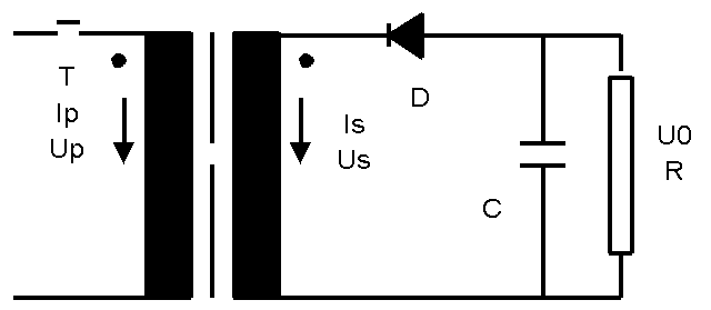
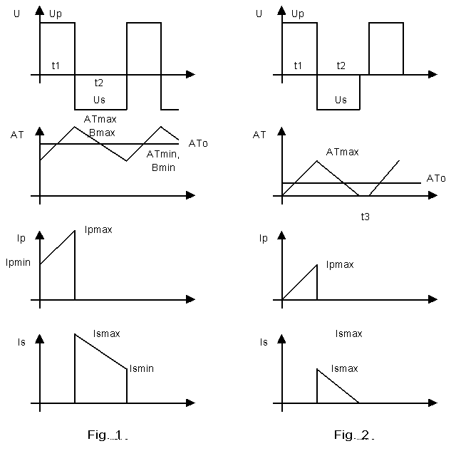
With a flyback transformer, the distinction is drawn between two modes of operation:
Mode with continuous induction ( Fig. 1, Bmin>0).
Mode with discontinuous induction (Fig. 2, Bmin=0).
Continuous mode (Fig.1)
In this mode, induction ripple is less than 100%:
Ripple = 100* (Ismax-Ismin)/(Ismax+Ismin) =(Bmax-Bmin)/(Bmax+Bmin) < 100
Due to the fact that the induction ripple is smaller than 100%, the core losses and the eddy current losses are smaller and can be controlled by designer. The typical input parameters for this operating mode are:
– Low steel losses
– Low eddy current losses: NO LITZ?
Discontinuous mode (Fig.2)
This is the most common operation mode because the flyback transformer is smaller than in the continuous operation mode.:
t1=t2 at minimal input voltage
Ripple => 100%.
Input only relevant to the design of a flyback
Criterion for design
Normally, high-frequency transformers have very low regulation and are designed according to the prescribed temperature rise. Since these transformers are manufactured almost exclusively using ferrite, the optimum operating temperature is around 100°C.
Bobbin
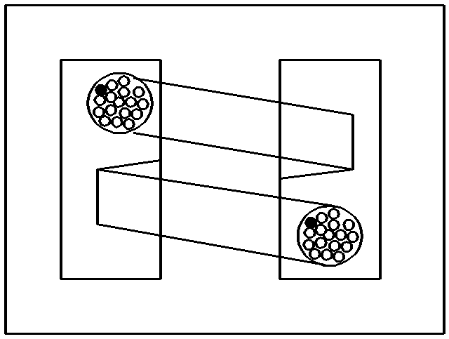
In order to protect the transistors, high-frequency transformers should be manufactured for low leaking reactance , with singlesection bobbin . For a good current distribution between 2 secondary windings they often require bifilar or interleaved windings.
Ferrite, Induction and Temperature rise
Since the optimum operating temperature of ferrite for high-frequency transformers is around 100°C and their ambient temperature is 40°C, our design assumption must be for a temperature rise of 60°K. The program calculates both the active and the reactive core losses by hypothesizing the ferrite type, the frequency, the form of input voltage, induction ripple, and core temperature. The induction should be selected so that the transformer does not saturate at minimum input voltage, maximum duty cycle and maximum core temperature. If the core losses in relation to winding temperature rise are not economically acceptable, then the computer program will optimize or reduce the AC-component (the ripple of the induction) automatically. But this indicates that the selected ferrite quality is not optimal.
Winding additional losses
With a high-frequency transformer, the distinctions are drawn between the following additional losses in a winding, over and above the dc-current losses:
- Eddy current losses
2. Skin effect losses
3. Proximity effect losses
4. Losses due to circulating currents through the parallel-connected wires.
The input for Rac/Rdc will limit the extent of additional losses. The program selects a high enough number of parallel-connected wires for the eddy current losses and skin effect losses to fall short of the prescribed value for Rac/Rdc. For that reason, the input for Rac/Rdc is also used for monitoring parallel-connected wires. The value is normally set between 1.25 and 3.
Losses of circulating currents through the parallel-connected wires are not calculated. It is assumed that these additional losses have been eliminated by suitable design precautions. In particular, it should be ensured, for a given litz, that the twisting for the winding maintains the same position at the input and at the output of the winding for any given winding.
Duty cycle at minimal input voltage
The duty cycle q is defined as follows:
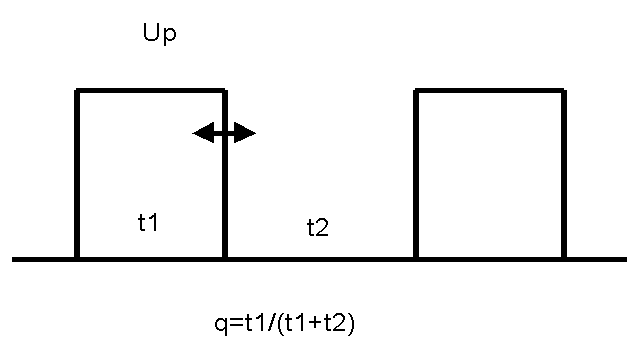
This flyback transformer with an automatic controller of output voltage and current ripple 100% is designed with the following parameters:
Upmin=125V
q_myx =0.7
Upmax=700V
q_min = 0.125
Procedure to design a 200W flyback transformer
Normally the user loads the standard input file for the flyback transformer and fills in the input mask in accordance with the discussion above. Note that all other parameters (such as chassis, insulation, case, impregnation,…) are generally relevant to the transformer design and will not be discussed:
Input voltage : U(V) = 125V
Duty cycle : Formfactor = 0.5/q_max=0.711
Ripple of the primary current (induction) : dI/Io = 100%
Output DC-voltage : Voltage = 2 x 24V
Output DC-current ; Current = 2 x 4A
Ambient temperature : Amb. Temp. = 40°C
Temperature rise : Temp. rise = 60°K
Induction = 0.275T
Single-section bobbin with the primary between 2 secondary : Bobbin = 11
Max. Build 50%: Space = 0.9
Factor for additional Cu-losses : Rac/Rdc = 3

Note that the core and bobbin are selected by hand.
If you double click over the input field Formfactor, you can calculate the formfactor for any form of the input voltage and the induction ripple.
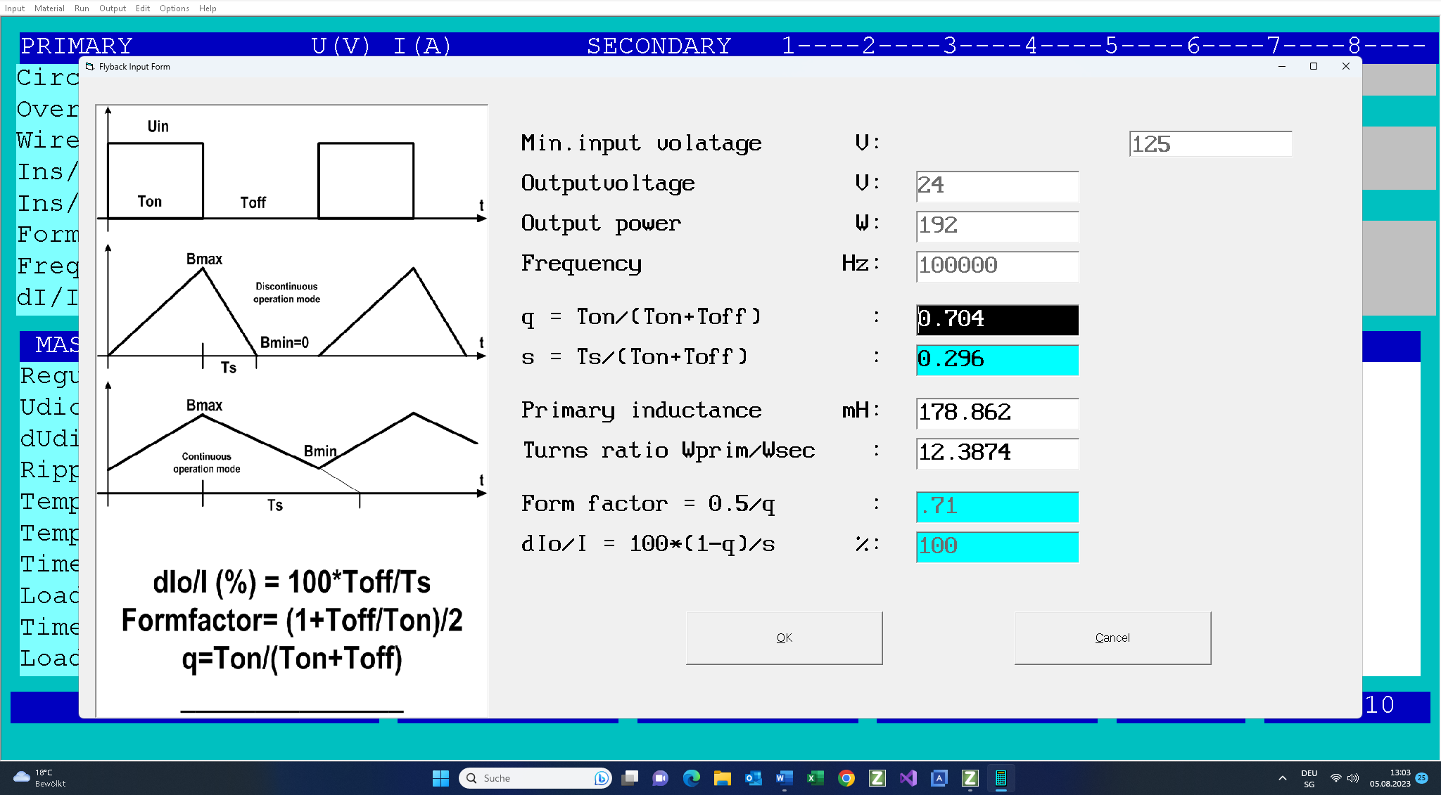
On completion of the design work, the following design data will be available, which can be saved and/or printed on 3 pages: InputPDF.
Checking the design
However, there are two parameters, which relate exclusively to the flyback transformer: primary winding inductance (187microH) and the gap (2×0.56mm) for calibration of the primary winding inductance at the nominal frequency.
The winding filling factor :54%<100% . If you would use round litz form the winding build would be 65-70%.
The maximum temperature of the windings is 40°C+62.2°K = 102.2°C < 115°C.
The number of parallel-connected wires (litz) for the secondary only is
100 x 0.15mm..The primary winding has 6 x 0.236mm.
Using the Test Mode
If the design data is not satisfactory, then you can access the test mode, modify the designed transformer manually (turns, wire size, steel, input voltage, load, duty cycle and redesign the transformer by that means. The following output mask in the test mode shows the results by checking the output voltage for the maximal input voltage of 700V and the duty cycle of 0.125: Uin = 700/125 = 5.55.
On completion of the design work, the following design data will be available, which can be saved and/or printed on 3 pages (click on the following link to obtain the PDF).
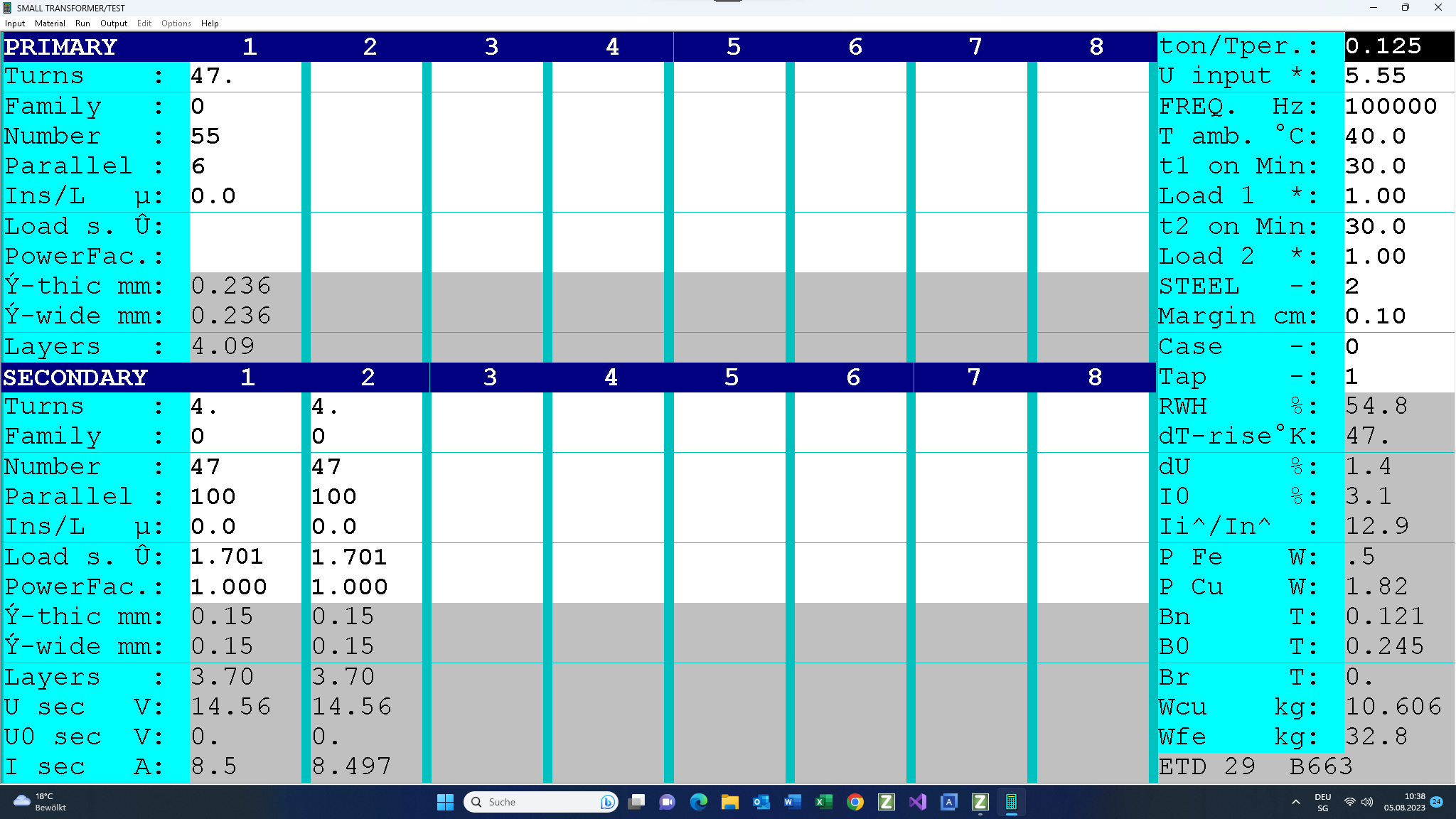
The following table shows the summary of the most important parameters, calculated by the program in the test mode. Note that the duty cycle (q) was changed in order to get the nominal output voltage that a voltage controller would give. Please click on the following link to obtain the PDF.
Finally here is the same design with induction ripple =20%, N27 and ETD 39.
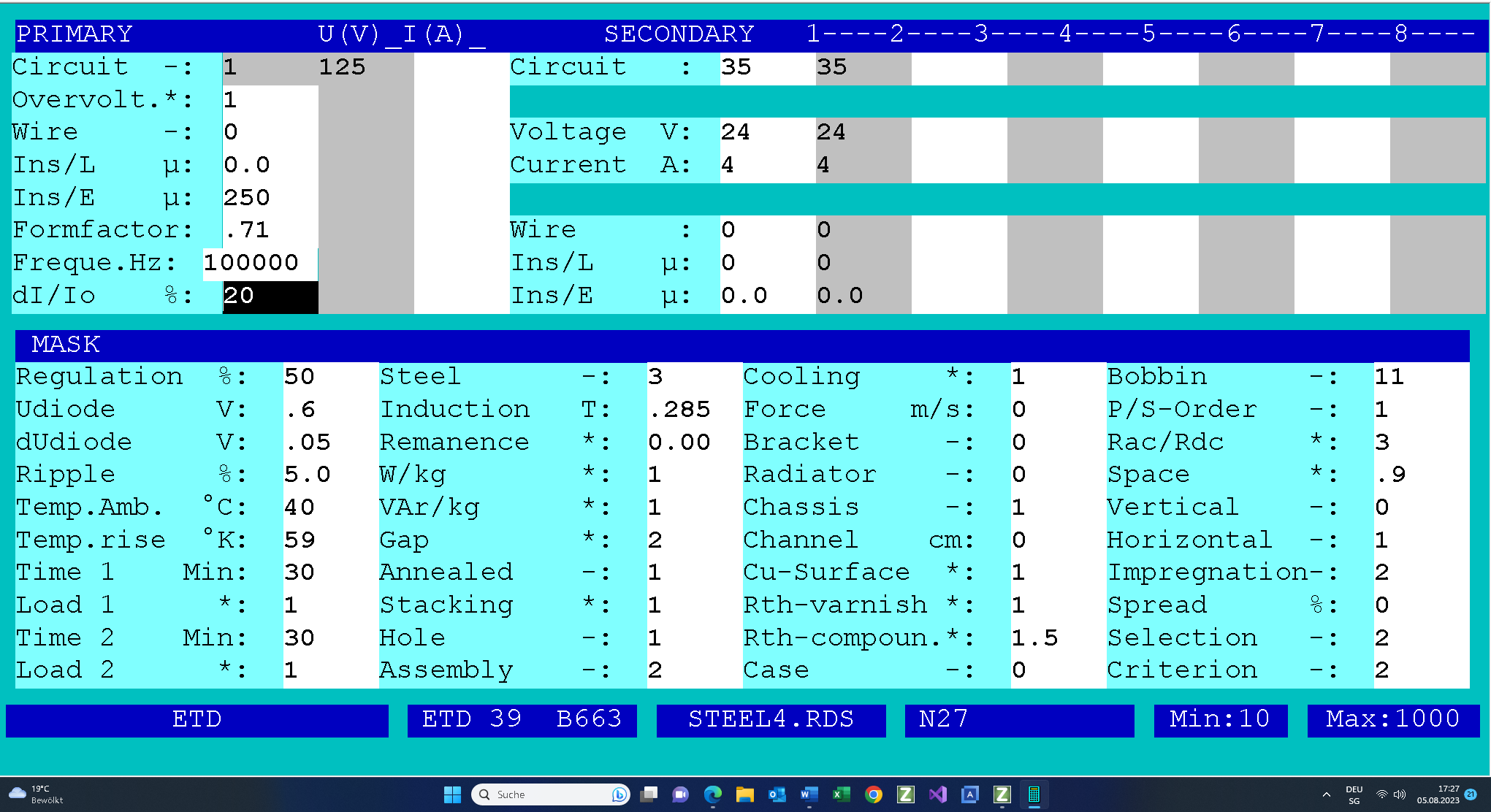
Click on the following link to obtain the PDF.