How should one design a motor starting
three-phase autotransformer
for 100kVA continuous motor power as per IEC 61558?
Technical specification relevant only to design
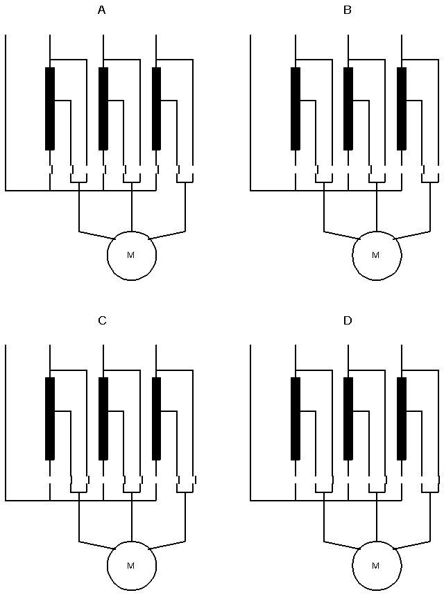
Electrical data and schema
| Input voltages sinusoidal | 3 x 400V (phase-phase) |
| Frequency | 50/60Hz |
| Nominal output voltage | 3 x 200V (phase-phase), normally between 50% and 70% of the input voltage |
| Nominal output current | 145A (100kVA) |
| Motor starting current | 2 .5 x 145 = 362.5A |
| Starting time | 10 seconds |
| Pause between two starts | 10 minutes |
Ambient and operating conditions
| Ambient temperature | 40°C |
| Mode of operation | Duty cycle, 10 seconds on, 10 minutes off |
| Test conditions | Non-inherently short-circuit proof, protected by a thermal fuse at 125°C |
Specifications
• Autotransformer as per IEC 61558
• Insulation class E


Normally the motor starting autotransformer has 2 output taps for 115V and 170V. The first tap at 115V is used only in the phase A. Operation at this tap is the worst case and it is used for design.
Tap 170V is used in the phase A and B.
Design criteria
An autotransformer with non-inherently short-circuit protection as per IEC 61558 is equipped with a internal protection. Very often, we arrive at a combined protection solution consisting of a primary-side fuse (short circuit protection) and a thermal fuse (overload protection). For this reason, short-circuit and overload is not design criteria. The criterion for design for purposes of IEC 61558 is only temperature Theta nominal at the overvoltage of 10%.
| Insulation class | A | E | B | F | H |
| Max. winding temperature in nominal operating mode Theta nominal (°C) | 100 | 115 | 120 | 140 | 165 |
Insulation class
Max winding temperature in nominal operating mode =115°C
Criterion for design
The autotransformer has to be designed for the temperature rise <75°K at 40°C ambient temperature, the overvoltage of 10% and insulation class E. The mechanical stress of the windings in short-circuit operation is normally in the power range up to 100kVA not criterion of the design. The criteria of design is the temperature rise: Criterion=2
Bobbin
An autotransformer is constructed exclusively with single-sectionr bobbin.
Induction and Fe-quality
A motor starting autotransformer is designed exclusively with cold-rolled steel M400, M800 at the induction approx. 1.6T.
No-load current
In order to avoid high voltage spikes between the operation A and B t §70V tap the no-load current of the autotransformer has to be approx. 25% of the motor nominal current. This can best be achieved if the core is constructed with a defined gap. Note that under this condition the continuous no-load operation isn’t normally allowed.
Input current
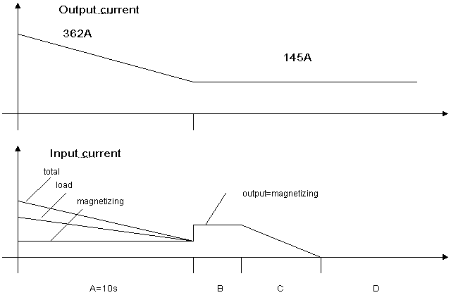
The output current during the operation A is not constant. Its rms-value should be entered in accordance with the following recommendation:
Load1 = (Imax/Inom+0.33*((Imax/Inom-1)^2))^0.5 = 1.8
Design procedure
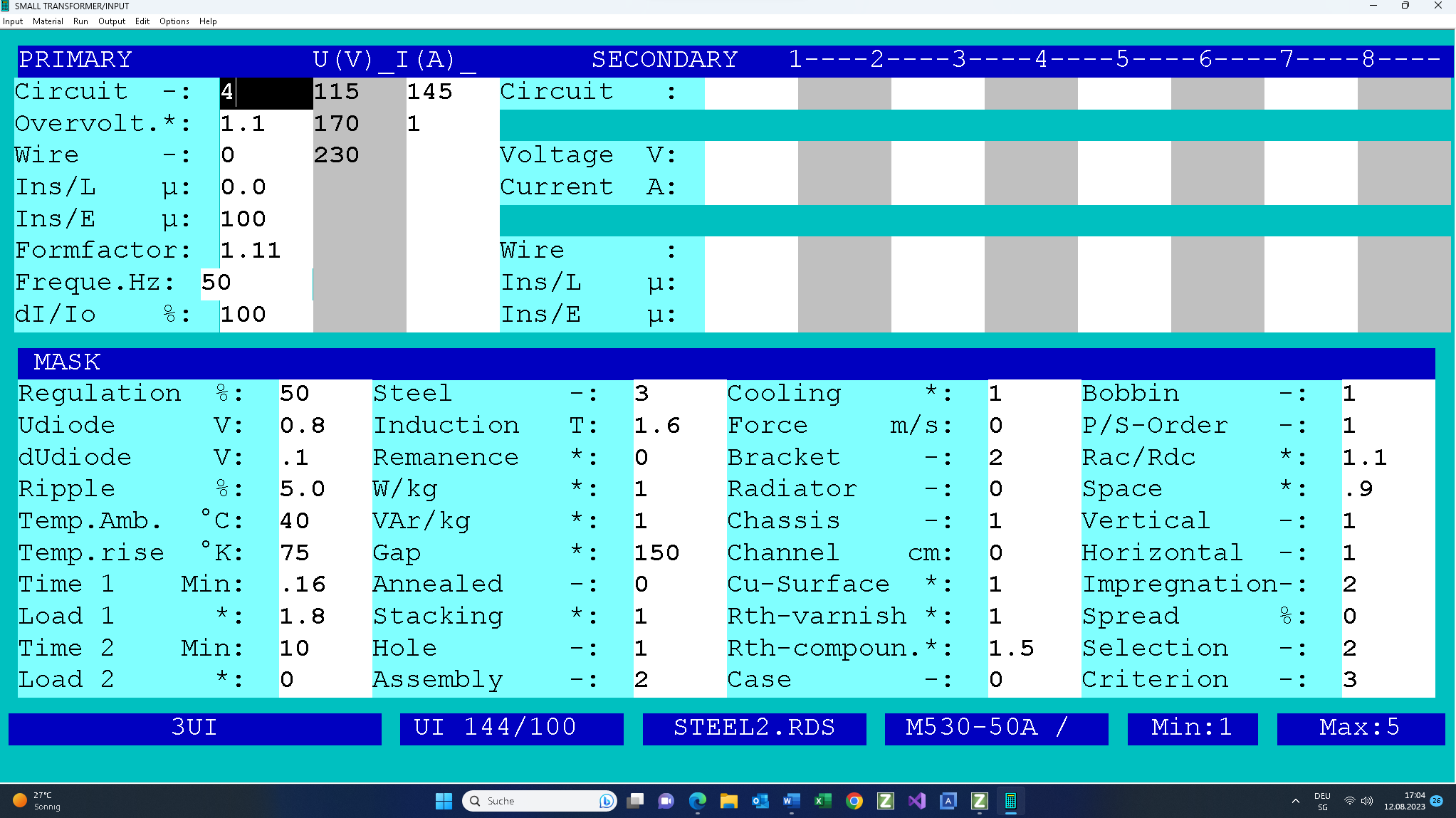
Fill in the design input mask as follows. If you need any help, press functions key F1. There is extensive description for each input field.

Note that the core&bobbin are selected by hand out of the data base.
Checking of the input data follows this.
The primary Circuit is set to 4 for the star connection of the windings. The Overvoltage = 1.1 means that the prescribed temperature rise of 75°K must not be exceeded at the 10% overvoltage of the primary voltage.
• Note that the core can be provided with one gap per limb if the core assembly is set to value 2. In order to get the value of the no-load input current approx. 25% of the autotransformer nominal current the core is constructed with a defined gap of ca 3.75mm mm (Gap = 150 x 0.025mm).
• The inputs Time1 = 0.166 minutes / Load1 = 1.8 / Time2 = 10 minutes / Load2 = 0 describe the motor starting operation.
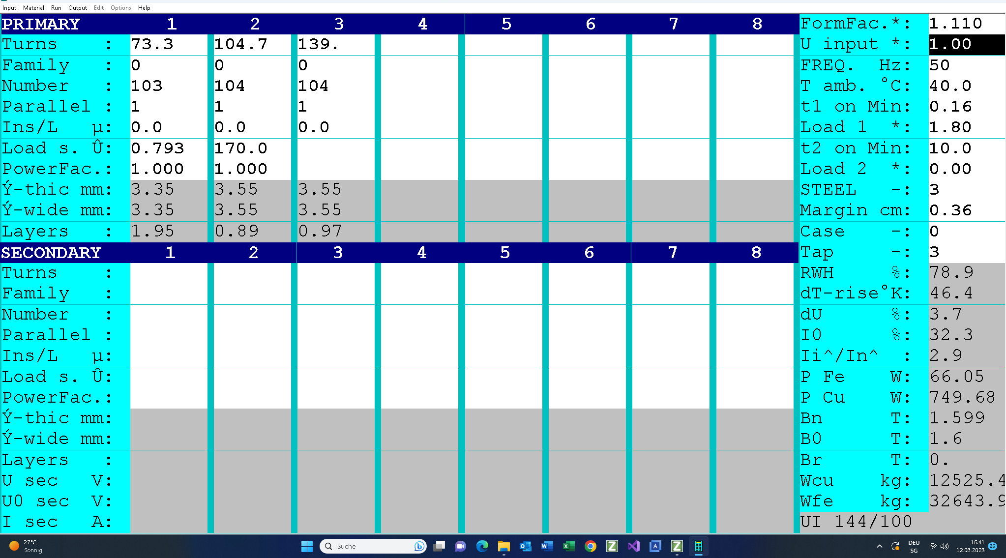
On completion of the design work, the following design data will be available and can be printed on the three pages (click on link to print PDF).
Checking of the design data follows this:• We now check the winding data and the filling factor (78<100%).
• The maximum temperature of the windings is 40°C+58°K = 98°C < 115°C . This autotransformer can be driven with some seconds longer or some ambers more..
• No-Load temperature rise is 170°K: NO-LOAD OPERATION is not allowed!
This is followed by checking of the output voltage at the nominal input voltage of 230V: Uin = 1.0

Print the PDF by clicking on this link.