CLICK HERE TO GET INPUT FILE: RaleInput_014
Designing non-short-circuit-proof,
low profile safety transformers up to 42VA
with Rale Design System,
in accordance with IEC 61558,
protected by miniature fuse as per IEC 127
Design criteria of a non-short-circuit-proof transformer
A transformer, which is not short-circuit-proof as per IEC 61558, is not equipped with any protection. However, the manufacturer is obliged to inform the user of the required safety measures by means of which the transformer must be protected in operation. In this case, the transformer should be protected by means of a miniature fuse as per IEC 127: the type and current rating of the fuse must be stated on the transformer label.
The procedure for designing and testing these transformers goes as follows:
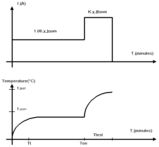
⦁ Firstly the transformer is connected to the rated supply voltage and loaded with an impedance which would give rated output current at rated output voltage and then the supply voltage is increased by 10%. Following this increase in voltage, no change is made in the circuit until the permanent-operating temperature is reached (Ton>>Tt). In this context, the temperature of the windings must not exceed the value of qnom (see the table below).
⦁ Immediately after this test the transformer is loaded for a period Ttest corresponding to the longest pre-arcing time with the relevant “impressed” current K*Ifnom as specified in the appropriate standard sheet. After the Ttest period, the temperature of the windings must not exceed the qtest values set out in the table below.
⦁ Finally, one output winding is short-circuited. At 1.10 times the nominal input voltage, the I2t-value of the fuse must actuate, before the temperature of the windings exceeds the values THETA test set out in the table below.
| Insulation class | A | E | B | F | H |
| Max. winding temperature in test THETA test (° C) | 200 | 215 | 225 | 240 | 260 |
| Max. winding temperature in nominal operation THETA nom (° C) |
100 | 115 | 120 | 140 | 165 |
To perform the calculations for a non-short-circuit-proof transformer, it is first necessary to select the miniature fuses.
As a rule, miniature fuses are placed on the secondary side, and if possible the nominal current for the Ifuse miniature fuse is selected to be approximately 10% higher than the nominal value of the Inom secondary current.
There are two distinct methods for the fuse selection:
⦁ The transformer should be protected with each miniature fuse type. Where the transformer has a thermal time delay of less than 10 minutes the test with Ttest = 30 minutes and K = 2.1 is crucial. Where transformers have a thermal time delay of over 10 minutes the Ttest>=60 minutes and K =1.5 (possibly 1.6) test should be applied.
⦁ The transformer should be protected by an inert T miniature fuse with low breaking capacity. Practical experience indicates that only the Ttest = 60 minutes with K = 1.5 (possibly 1.6) criterion should be applied.
Insulation class
In these output ranges, the bobbins, the case and the potting compound are employed exclusively together with insulation categories E and B. Wire insulation and insulation foils are very often employed in insulation class F.
Ambient temperature
Normally, the transformer is operated in an environment of which the temperature is between 40°C and 70°C.
Case
For safety reasons, low-profile-constructed safety transformers are almost exclusively potted in vacuum in a case. The main advantages of a potted transformer are:
The transformer is cooled better.
You can use a bobbin without great wall thickness and without large leakage paths, but with a larger winding space.
Chassis
The non-short-circuit proof, low profile transformers are intended exclusively for the printed board. In order to have good thermal contact with the print, the transformer needs to be “fully” potted so that the air gap between the compound and the print is maximum 0.2 –0.5 mm.

Thermal resistance of the potting compound
The potting compound which is best from a thermal viewpoint, and also the most expensive, has a specific thermal conductivity of 0.8W/m/°K. In practice, we usually operate with a potting compound whose thermal conductivity is 0.4/W/m/°K.
Bobbins
In this output power range, recourse is made almost exclusively to a double-section bobbin. From the viewpoint of design, only the dimensions of the bobbin are important. A bobbin with increased insulation or large leakage paths has a smaller winding space and a smaller cooling surface area.
Steel
A flat transformer must be as flat and as small as possible. For that reason, these transformers are manufactured exclusively in UI sheet form without holes in the corners and annealed, grain-oriented core quality with specific Fe-losses of 1.11 W/kg at 1.5T and 50Hz (WV111, M6, etc.).
Induction
These transformers are manufactured with an induction in nominal operation between 1.5T and 1.7T (!). No-load induction is normally above 1.8T. For that reason, we must use an annealed, grain-oriented core quality without holes in the corners.
Tolerance for output voltage
The output voltage of a not short-circuit proof transformer is tested in the hot state at nominal primary voltage and nominal load resistance and may vary by +-5% of the rated value. If 2 (typical of UI core) or more secondary coils are present, the permitted tolerance is +-10%.
Secondary coil circuitry
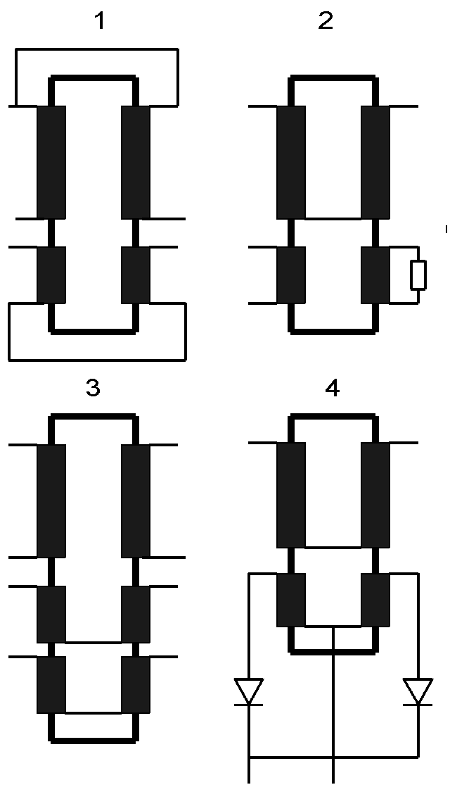
The transformer usually has a primary and secondary coil on each leg. All the coil connections are accessible from the exterior and are used for serial and parallel circuits. The first picture in figure 3 shows the serial circuit. The ampere turns of the primary and secondary coils per leg are compensated. If the transformer is used as shown in pictures 2 and 4, the ampere turns per leg are not compensated and the transformer diffuses a magnetic field that is 5-10 times greater. Picture 3 shows the design and internal wiring of the secondary coils at which the ampere turns per leg always remain compensated.
Procedure for design
The calculation example shown below explains the calculation procedure in brief.
Technical specifications relevant only to design
Electrical data
| Input Voltage | 2 x 115, +10%,-10% sinusoidal |
| Frequency | 50/60Hz |
| Nominal output voltage | 2 x 12Vac |
| Nominal output current | 2 x 0.75Aac, protected by 2 x 0.8A miniature fuse |
Environment and operating conditions:
| Ambient temperature | 70°C |
| Mode of operation | Continuous |
| Test conditions | With non short-circuit-proof, protected by 0.8A miniature fuse K=2.1, 60 minutes |
Specifications
– Safety transformer as per IEC 61558
– Insulation class E
– Potted in case
– Core and bobbin UI 39/13.5. Note that this core is selected by hand.
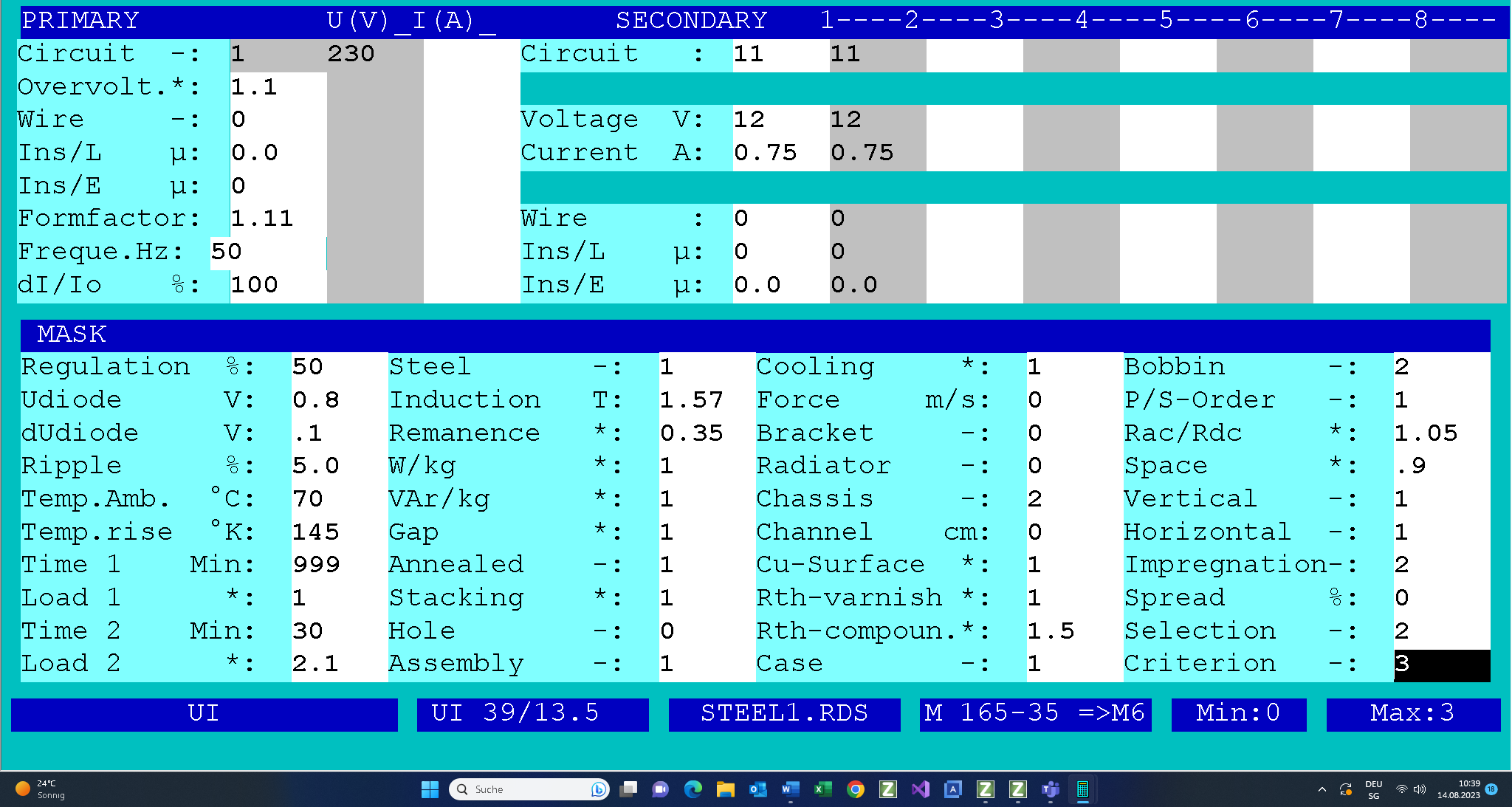
This is a brief description of the input mask illustrated above:
Two secondary coils are designed for 12V, 0.75A, in warm conditions, at an input voltage of 230 V, 50 Hz.
The transformer is fed at an ambient temperature of 70 degrees C (Amb. Temp. = 70) first of all under overvoltage (overvoltage = 1.1) of 10% for a very long period (Time1 = 999 minutes) at a rated load resistance (Load1 = 1). The transformer is then loaded for 30 minutes (Time2 = 30) at 2.1 times the nominal fuse current (Load2 = 2.1). Once the 30 minutes have expired the transformer should reach an over-temperature of 135 degrees (K Temp. rise = 135).
The core U139/13/5 of M6 steel (Steel = 1) nested on either side has two double section bobbins (Bobbin = 2) and is potted in a case (Case = 1) with a compound of 0.4W/K/m (Rth-compound=2). The transformer is placed on a printed board (Chassis = 2).
Note that you can select the core and bobbin with the case. If the record for the core and bobbin which you selected has no case, then you have to set up the case yourself. The core selected in the following illustration has a case in its record. For this reason, it is enough to mark the core UI39/13.5 and to click on the OK button.
After the design procedure has been completed, the following design data is available and can be printed on 3 pages.
Note that both secondary windings have to be wound BIFILAR!
Check
This is followed by a check of the calculated data.
⦁ Firstly, we check the maximum winding temperature in nominal operating mode = ambient temperature + dTprim in nominal operating mode = 70+38 =108 < 115°C
⦁ The maximum winding temperature in the test mode is:
ambient temperature + dT primary = 70 + 132 = 202<215°C
⦁ The average case surface temperature in the test mode is:
Ambient temperature + dT case in test operation = 70 + 97.9 = 169.9>105°C
This means that this transformer has to be installed in a unit such that it cannot be touched during operation.
The winding temperature in the test mode is:
Ambient temperature + dT winding in test operation = 70 + 132 = 202<215°C
This is followed by a check of the calculated data under the nominal input voltage:
Click on this link to obtain PDF.
Test Mode
In the test mode the transformer can be checked in the same way as on a test rig in a lab, and if necessary be altered manually.
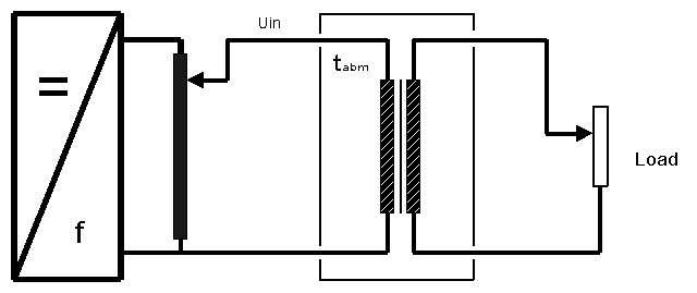
The secondary windings are short connected by settings the load resistance to 0.001 Ohms.
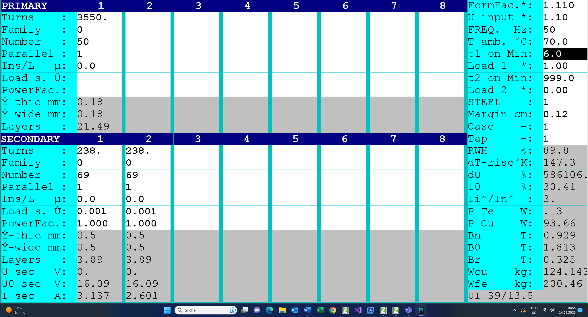
After 6 minutes the transformer temperature was 215°C: the I2t of the primary fuse has to be smaller than o.56^2 x 6 x 60.