CLICK HERE TO GET INPUT FILE: RaleInput_107
Designing a 1600kVA/35kV, 50Hz Distribution Oil Transformer and Oil Tank
General Information
In this design the secondary winding is made with Al foil.
The primary winding is made with Al rectangular wires, wound over the smaller wire dimension in 4 layers. In this winding construction the high voltage pulse distribution is uncritical.
Technical Specifications
| Input voltage | 3 x 35000/20230V, star sine wave |
| Transformer output voltage | 3 x 400/230V, star |
| Line output current | 3 x 2319A, continuous operating mode |
| Frequency | 50Hz |
| Ambient (air) temperature and Min. oil temperature rise |
25°C
35°K |
| Max. winding temperature rise and/or max.winding losses at 75°C |
65°K
18000W => 1.125% |
| Short-circuit voltage | 6.5% |
| ° | |
| Max. core losses | 3200W => 0.2% |
| Max. oil temperature rise at 21200W | 60°K |
| Max. no-load current | 1.3% |
| Test Voltage at 50Hz, 1 minute | Primary 85kV, outside Secondary 4kV, inside |
| Steel & Core Assembly | 30P110, annealed, strips for alternated stacking (4×45°+3×90° per shape) “round” cross section with 8 steps |
| Core Size | Optimized for minimal material price for:
Al_Price/Fe_Price = 1 with Al-winding |
Creating Input
4 input screens are used to set the input parameters for designing a transformer:
- Winding parameters per limb
- Core
- Environment
- Other.
and 3 screens for selection and set up of material :
- Wires
- Steels
- Cores.
Criteria and Parameters of Design
The design of a distribution transformer is always framed by 5 criteria which have to be put into effect simultaneously:
- Short-circuit voltage
- Winding losses at 75 °C
- Winding temperature rise
- Core losses
- No-load input current.
Under this condition the first step is the optimizing the core size to match the above mentioned prescribed design criteria for the optimal material price using some additional parameters such as:
- Cooling media
- Testing voltages
- Steel quality and core assembly
- Winding type and wire type & material
- Cu/Al and Fe price relationship (per kg).
Normally the user of this software will create an optimized core family for a typical design criteria and parameters and select a desired core per click. In order to demonstrate the procedure for core optimization, note that the following parameters of optimization are a summery of 5-6 designs:
- Max. winding losses at 75 °C = 18000W
- Inductive short-circuit voltage = 6.4%
- Max.winding temperature rise 65°K at the ambient (air) temperature 25°C
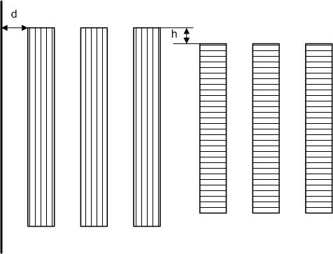
For the winding losses 18000W with the winding temperature rise to the average oil temperature of approx. 15-20 °K both windings need to have very big cooling surface using min.of 3 vertical cooling channels in both windings. The used windings construction is presented in the next picture. It is optimal because there is no need for any transposition within the high current winding and there is no need to worry about the pulse voltage distribution and partial discharging between the layers within the high voltage winding.
In order to avoid very high circulated losses within a foil winding (max. 5% is a good value) you need to follow these rules:
- Use Al-foil instead Cu foil. Note that max. allowed mechanical pressure in Al foil in a short circuit operation mode has to be smaller than 20N/mm2.
- In order to reduce the radial magnetic field on the top & bottom of the foil winding set the distance h > 0 (normally between 15-30mm)
- Increase the distance d between the leg and the first foil winding
The high voltage winding has to have only 4 layers with 6mm cooling channel between them. Due to this fact the rectangular wire has to be wound over the smaller wire side. Normally this winding type has higher eddy-current losses but using Al-rectangular wire the eddy-current losses can be easy limited to max 10-20%
- Max. core losses = 3200 W
- Max, no-load current = 1.3%
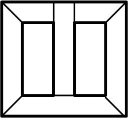
These 2 criteria of design can be easy realized with annealed strips of 30P110 (M110 H,30ZH110, …) grain oriented steel at the induction 1.75T with the following shape and 8 steps “round” cross-section:
For 85kV, 50Hz, 1 minute high voltage test and the power 1600kVA the following min. spacing is recommended:
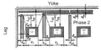
a01=17mm; a12=27mm ;a22=30mm
δ01=δ12=5mm (tubes)
δ22=3mm ; δш=2mm ( 2 x overlapped to increase the creaping distance to the yoke)
l01=l02=75mm
lц1=lц2=50mm (tube width over the windings)
Note that the creeping distances between the HV-windings and the LV-windings & the core have to be bigger than 125mm.
Windings parameters per leg
Primary
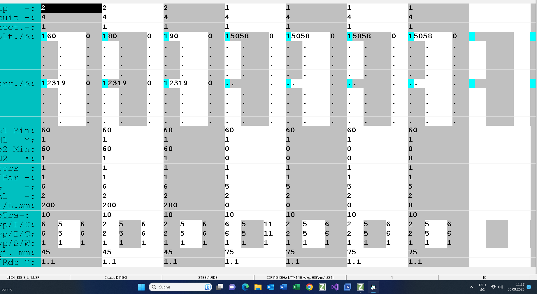
The primary is created in star connection. The sine wave input voltage is 20230V .
There are no voltage harmonics and there is no duty cycle operation mode.
The primary will be manufactured with Al-flat wire in cylindrical winding technology (view picture above) with 3 vertical cooling channels of 6mm between 3 layers. The advantage of this winding configuration is low voltage per turn and no problems with partial discharging and pulse voltage distribution. In order to suppress the effect of the high pulse voltage you can add easely stronger insulation to the10 first and 10 last turns of the winding.
Secondary
The secondary winding is set inside. It is wound with Al-foil and 0.2mm insulation between the turns. In order to increase the cooling surface the secondary is cut in 3 coils. Between them are 6mm cooling channels. Due to the fact that the first winding to the leg has higher circulated currents than 2 other coils its number of turns should be smaller than the number of turns of 2 other coils.
The sine wave output voltage is 230V.
The rms output current is 2319A. There are no current harmonics.
Also, there is no duty cycle operation mode on the secondary.
With the eddy current losses factor (RacRdc) 1.1 the number of parallel wires & foils will be limited. Note that at this point of the design you cannot prescribe the wire or foil size. You can select only the wire family which the program must use in order to select the suitable wires or foil for your application.
Core
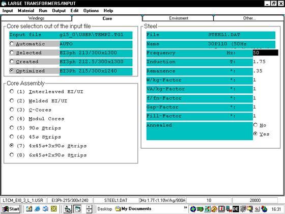
On this input screen you can:
- select and manipulate the selected steel 30P110 (M 111 H, 30ZH110, 30H110). This steel has the losses of 1.1W/kg at 1.7T, 50Hz 1nd >1.88T at 800A/m;
- set the operating induction (1.75T) and the frequency (50Hz);
- select the core assembly 7 (view the picture above);
- and prescribe the core selection out of an input file. This option will not be used because the core size has to be optimized by the program.
Environment
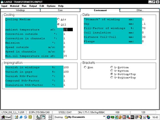
The ambient (air) temperature is 25°C
The cooling medium is oil with the minimum oil temperature rise on the oil tank bottom of 35°K Note that this temperature rise has to be fine-tuned during the oil tank design in the Test Mode.
The cooling surface of the core is increased by using 4 L-brackets on the core. The minimum distance between the primary outside coils of 2 phases is 30mm. There is no flange but both windings have to be fixed in order to suppress the axial forces during the short circuit operation mode.
There is no air in the windings nor the gaps between the windings and insulations!
Other
Here you can set the criteria for design (winding temperature rise or winding losses at any temperature) and/or the criteria for optimization for the minimum of the material price.
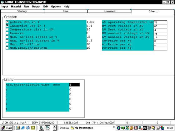
The selected criteria of the design and core optimization are the winding losses (18000W => 1.125%) at 75 °C and the inductive short-circuit voltage 6.4%. Note that the program can NOT optimize (but it can calculate) the losses of the circulated current in the foil changing winding material and spacing because this has to be set by designer only. Due to this fact the prescribed windings losses are set to 1.05% instead 1.125%
If you prescribe also the winding temperature rise then the program has to use the criterion which is more critical: either the winding losses or the winding temperature rise with the prescribed inductive short circuit voltage.
The core losses and the no-load input current can be manipulated only with steel quality, core assembly and induction
If the ratio of the price per kg between the windings and core material is 1 then the transformer is optimized for minimum price and weight.
Core optimization
After you have set all input screens you need to select a core family and a core as template: 3 phase core family with 8 steps “round” cross section.
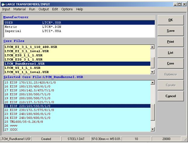
Click Core to open the input screen for reading the parameters of the selected core:
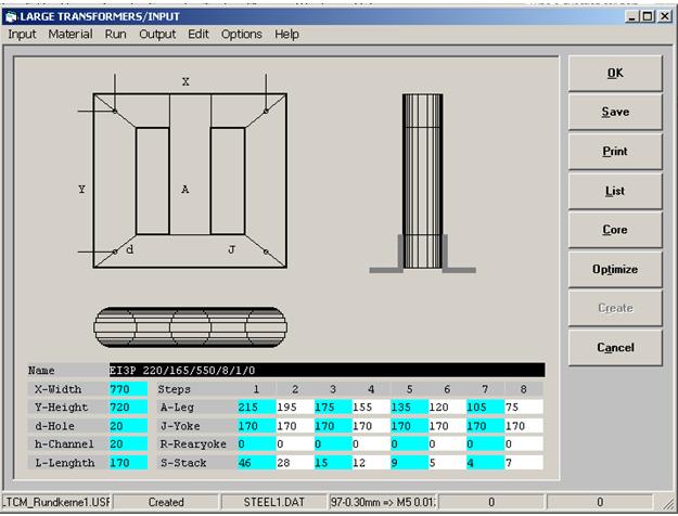
Click Optimize to optimize the core.
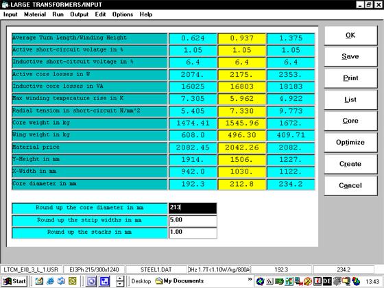
The yellow output fields are optimal results. Both other columns have a higher material price for 2%.
At this point you have to check whether the active and inductive core losses are within the prescribed range:
Active core losses = 2239W < 3200W
Inductive core losses = 23216Var <24000VAr
The next check is the value ofthe radial mechanical forces during the short-circuit operation mode:(7.132 N/mm2 < 20 N/mm2, max. allowed for Al) and the average winding temperature rise to the average oil temperature (5.0952°K < 15°K)
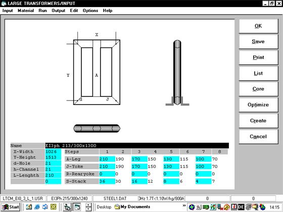
Here you can round off the core diameter (210mm instead 206) and click Create. This is the optimized core: Created D 210/8.
Output
The first step of the presentation of the output screen is the DIAGNOSIS: It is the summary of the most important calculated parameters of your transformer.
Before you use the information on this page this design has to be modified by hand:
-The number of turns has to be rounded to integer values.
– The foil widths thicknesses have to be set to values which can be bought.
– The primary winding has to have one layer.
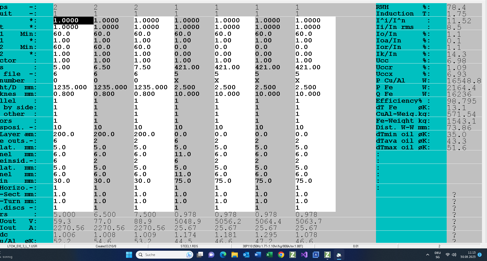
Here is the result in the test mode:
You can print the results by clicking on the following link.
Here are some remarks to this design:
- Very simple winding construction.
- Winding losses 16504W < 18000W
- Reactive short-circuit voltage 6.9%> 6.4%
- Windings temperature rise 55°K < 65°K
- Max. oil temperature rise 55°K < 60°K
- Core losses 2134W < 3200W
- Reactive core losses 16092 < 1.3%
Oil Tank
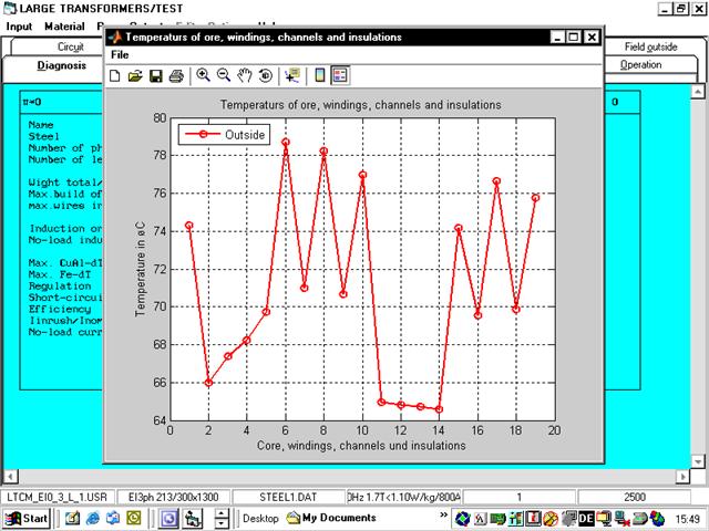
During the transformer design the minimum oil temperature rise on the bottom of the oil tank (common for all windings) was set to 35°K. The calculated transformer and oil temperatures are presented in the following diagram:
Legend:
- 1 => Core
- 2,5,7,9,11,14,16,18 => average oil temperature in the cooling channels
- 3,4,12,13 => surface of the insulation
- 6,8,10,15,17,19 => average winding temperature
Note that the program calculates the max. oil temperature and the oil flow (the amount per second) in the cooling channels and the max. oil temperature on the top of the oil tank as the average value of the mixed amounts of the oil on the exits of the cooling channels. In this case the max. oil tank temperature is 80.58°C (the temperature rise 55.58°K<60°K)
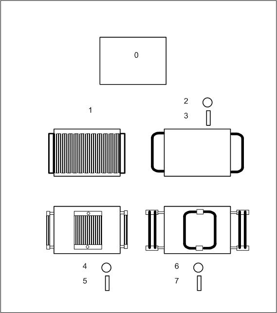
From the thermal point of view the program supports the following 8 types of oil tank cooling:
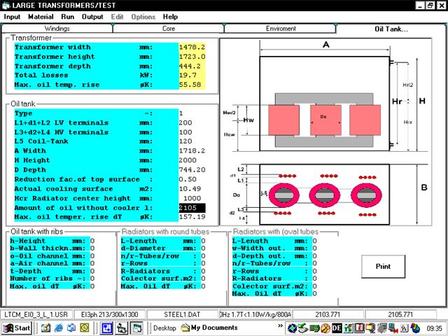
In the first step you need to set the size of the “naked” oil tank. For your reference the dimensions of the calculated transformer are presented on the top of the input screen. The result of your settings in this input frame are the oil tank dimensions, the amount of the oil and the max. oil temperature rise of the “naked” tank. Note that the amount of the oil is calculated without the coolers (fins, tubes and radiators).
The next step is the setting of the cooler. In this case the selected cooler is with cooling fins:
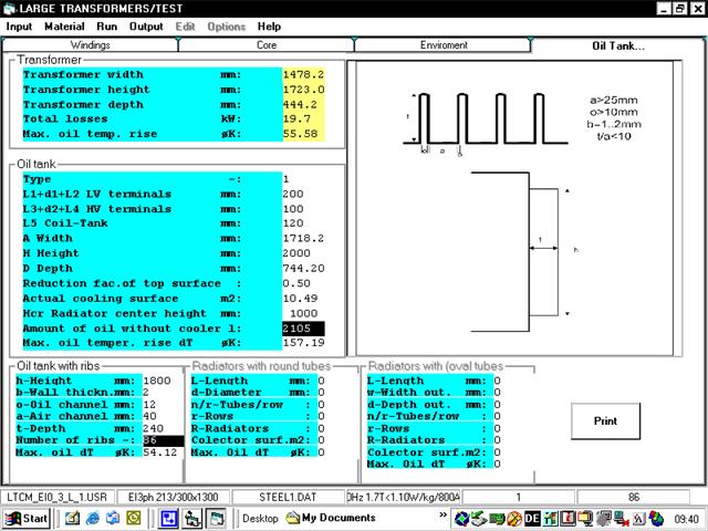
After you set the size of the cooling fins the program will calculate the max. available number of the fins and the max. oil temperature rise. You can change the fin size or reduce the number of fins in order to get max. oil temperature rise approx 55.58°K. If you set the max. oil temperature rise at 60°K (changing the cooling fins) then you need to redesign the transformer with the min. oil temperature rise 39.42°K (instead 35°K).
Circulated Current Losses
Note that the program uses the numerical calculation of the magnetic fields. Due to this technology the calculations of the circulated current losses is very powerful.
The following pictures show the magnetic field inside of the core window by the margin of the secondary winding 75mm and 45mm. You can see that the radial magnetic field through the top of the secondary winding is stronger with the margin 75mm and the circulated current losses higher:
- The primary margin=75mm, the secondary margin=75mm => the circulated current losses = 1300W/phase
- The primary margin=75mm, the secondary margin=45mm => the circulated current losses = 220W/phase