CLICK HERE TO GET INPUT FILE: RaleInput_009
How should one design a 50kHz, 1200VA transformer
as per IEC 61558 ?
Technical specification relevant only to design
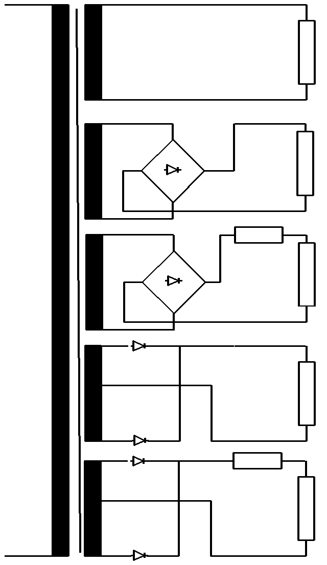
Electrical data and schema
| Input voltages | Max. 280Vac, square-wave |
| Frequency | 50kHz |
| Nominal output voltage 1 Nominal output current 1 |
24Vac 10Aac |
| Nominal output voltage 2 Nominal output current 2 |
24Vdc, bridge rectifier with R load 10Adc |
| Nominal output voltage 3 Nominal output current 3 |
24Vdc, bridge rectifier with RL load 10Adc |
| Nominal output voltage 4 Nominal output current 4 |
24Vdc, central tapping rectifier with R load 10Adc |
| Nominal output voltage 5 Nominal output current 5 |
24Vdc, central tapping rectifier with RL load 10Adc |
Ambient and operating conditions:
| Ambient temperature | 40°C |
| Mode of operation | Continuous |
| Test conditions | Non inherently short-circuit proof |
Specification
- Insulation class E

Criteria for design
A high-frequency transformer with non inherently short-circuit proof as per IEC 61558 is equipped with a safety. Very often we arrive at a combined protection solution consisting of a thermal fuse in the primary winding and cut-out electronics in the cycled mains power unit to protect against overload and short-circuit. For this reason, short-circuit and overload are not design criteria. The criterion for design with regard to IEC 61558 is only temperature Tnominal.
|
Isolation class |
A |
E |
B |
F |
H |
|
Max winding temperature in test q max (° C) |
200 |
215 |
225 |
240 |
260 |
|
Max winding temperature in nominal operating mode q nominal (° C) |
100 |
115 |
120 |
140 |
165 |
Isolation class E
Max winding temperature in nominal operating mode = 115°C
Max winding temperature in test mode = 215°C.
Note that the thermal fuse is set at 125°C.
Criterion for design
Normally, high-frequency transformers have very low regulation and are designed according to the prescribed temperature rise.
Since these transformers are manufactured almost exclusively using ferrite, the optimum operating temperature is around 100°C.
Bobbin
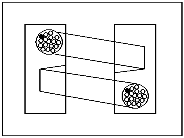
In order to protect the transistors, high-frequency transformers should be manufactured for low leaking inductance, with single section bobbin units. For this reason, we very often arrive at litz-wire or interleaved primary and secondary windings.
Ferrite quality
Since the optimum operating temperature of ferrite for high-frequency transformers over 100VA is around 100°C and their ambient temperature is between 40°C and 70°C, our design assumption must be for an temperature rise of between 30°K and 60°K. If the core losses in relation to temperature rise are not economically acceptable, then the program will optimize or reduce induction automatically. But this does indicate that the selected ferrite quality is not optimized.
Induction and ferrite quality
High-frequency transformers are equipped almost exclusively with ferrite. The program calculates both the active and the reactive core losses by hypothesizing the ferrite type, the frequency, the form of input voltage, induction and core temperature. The induction should be selected such that the transformer does not saturate at maximum input voltage and maximum core temperature.
Winding additional losses
In a high-frequency transformer, additional losses occur in the windings due to the uneven distribution of the current across the conductor cross-section
The input for Rac/Rdc will limit the extent of additional losses (eddy current losses and displacement losses). The program selects a high enough number of parallel-connected wires to limit the eddy current losses and displacement losses to the prescribed value for Rac/Rdc. For that reason, the input for Rac/Rdc is also used for monitoring of parallel-connected wires. The value is normally set between 1.3 and 5.
.

Procedure for design
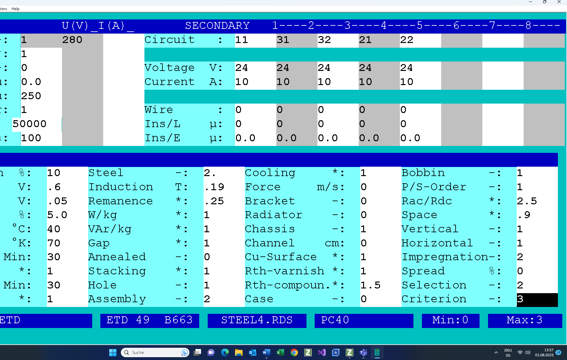
Fill in the design input mask as follows. If you need any help, press function key F1. There is extensive description for each input field.

Note that the core&bobbin are selected by hand.
On completion of the design work, the following design data will be available and can be printed on three pages (click on the link to get the results on a PDF).
This is followed by checking the design data:
- We now check the winding data and the filling factor (61%<100%).
- The maximum temperature of the windings is 40°C+66.5°K = 106.5°C < 115°C.
- The number of parallel-connected wires with 0.19 mm diameter is 40 (primary) and 80. (secondary windings) .. This operation must be performed manually in the test mode.
- In the test mode, furthermore, the number of windings of the secondary is manually rounded up from to 3 turns.
If the design data is not satisfactory, then there are two ways by which we can implement the desired correction:
- You can return to the input mask (function key F2), correct the input data and redesign the transformer.
- Or you can access the test program (function key F5), modify the designed transformer manually and redesign the transformer by that means.