GET THE INPUT FILE HERE (CLICK): RaleInput_304a
Single Phase Commutation Choke
The commutation choke is connected in the front of rectifier, on the AC sid, in order to limit the current rise during current commutation between phase and neutral line (short circuit operation mode over the commutating choke).
In order to limit the DC voltage drop to 3-4%, the short circuit voltage has to be between 4% and 6%.
Note that the non-linear RC&RL&R rectifier load, with or without DC current smoothing choke, is the source of high current harmonics between 150Hz and 1000Hz. The size and the frequency range of the current harmonics depends on the DC output power amd the rectifier type (View the design example about rectifier transformers).
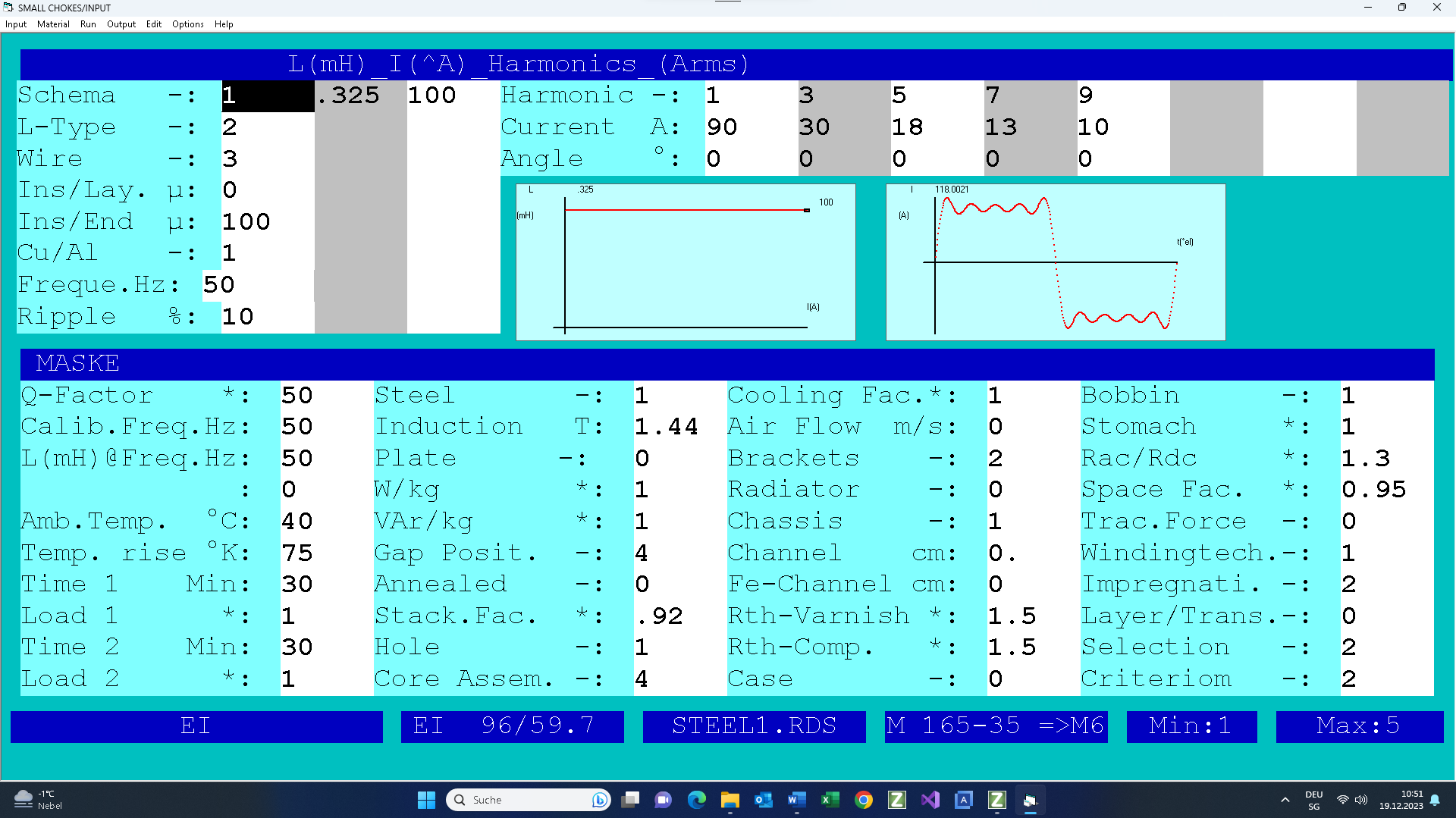
Here is the design example about the single phase commutation choke in front of the bridge rectifier with the DC current smoothing choke.

| Harmonic k | I21k.rms/Idc | Angle | I22k.rms/Idc | Angle |
| 1 | 90 | 0 | ||
| 3 | 30 | 0 | ||
| 5 | 18 | 0 | ||
| 7 | 13 | 0 | ||
| 9 | 10 | 0 |

TEST
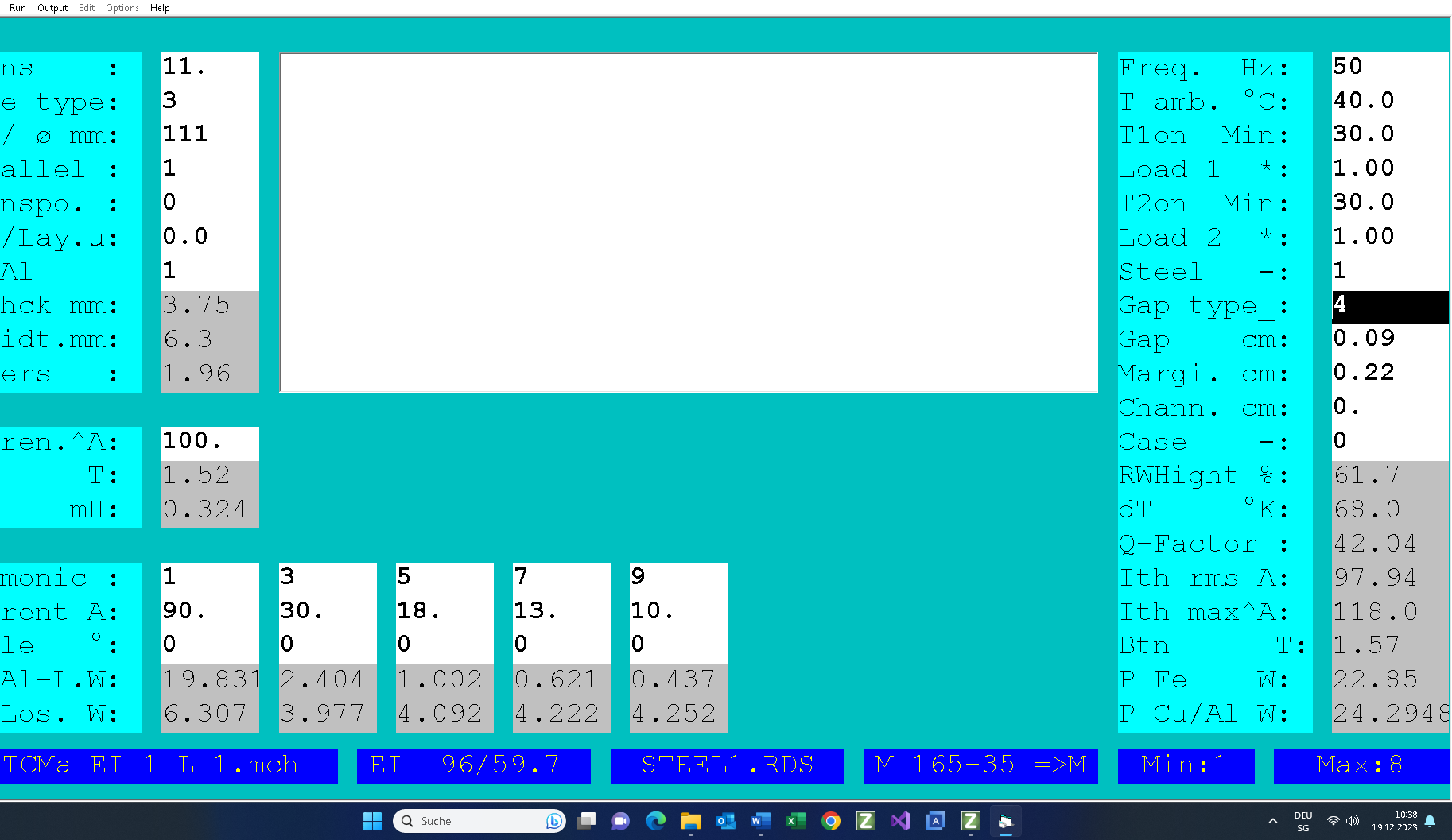
In the Test mode you can modify the caöculated parameters by hand:
– Turbs
– Wire size
– Use more wires&foils in parallel
– Ambient trmperature
– Gap
– Steel
– Currents

Here is the result of the design; you can print it.