
Designing a non resonant high voltage, single phase, oil transformer, class =<0.5%
Input: 22kV, Test voltage 50kV,,50Hz_1min,BIL 100kV, Cu multi layer winding
Output: 2x110V,1.45A,4 Cu -single layer windings with “S1/2-S2/2-P-Screen-S1/2-S2/2” order of windings
About high voltage transformers
The main problem is BIL impulse voltage of 100kV. Due to the fact that the primary round, double insulated wire is very small, the impulse voltage distribution factor is very high and the max. voltage between 2 primary turns can be higher than the breakdown voltage. Additionally, the resonance can increase the voltage per layer. To avoid these problems, we are using the screen on the outside of the primary. The screen is one turn foil winding. It is connected with the primary winding.
On the start of 100kV-impulse the capacitive current between the screen and the primary winding has to compensate the capacitive current between the primary winding and the ground. The result of this compensation is a low distribution factor and a low maximal voltage between 2 primary turns.
In order to support the no liad operation mode of one secondary and to limit the inductive short circuit voltage, we have the following order of the transformer windings:
– Transformer has 2 secondary windings: S1 and S2. 50% of each secondary winding is wound inside and other 50% is wound outside to the primary winding.
– The primary winding and the screen are wound between 2 secondary groups.
Technical parameters
|
Input voltage
Test voltage
BIL |
Max. 22000 50kV, 50Hz, 1 min
100 KV |
| Transformer output voltage | Max. 2 x 110V |
| Output current | 21 x 1.45A, continuous operating mode |
| Frequency | 50Hz |
| Class Design criterion |
<0.5% Load losses Ucca =0.85% |
| Steel Nominal induction |
GO 23P90 1.5T |
| 2 loops C-core | Leg: 60x60mm,voke:30x60mm,2 windows: 240×100 |
| Ambient temperature | 25°C |
Creating Input
4 input screens are used to set the input parameters for designing a transformer:
- Winding parameters per leg
- Core
- Environment
- Other
and 3 screens for selection and set up of material :
– wires
– steels
– cores.
At this point we are recommending you to open the input file: INPUT_FILE_HVT_SSPSS.
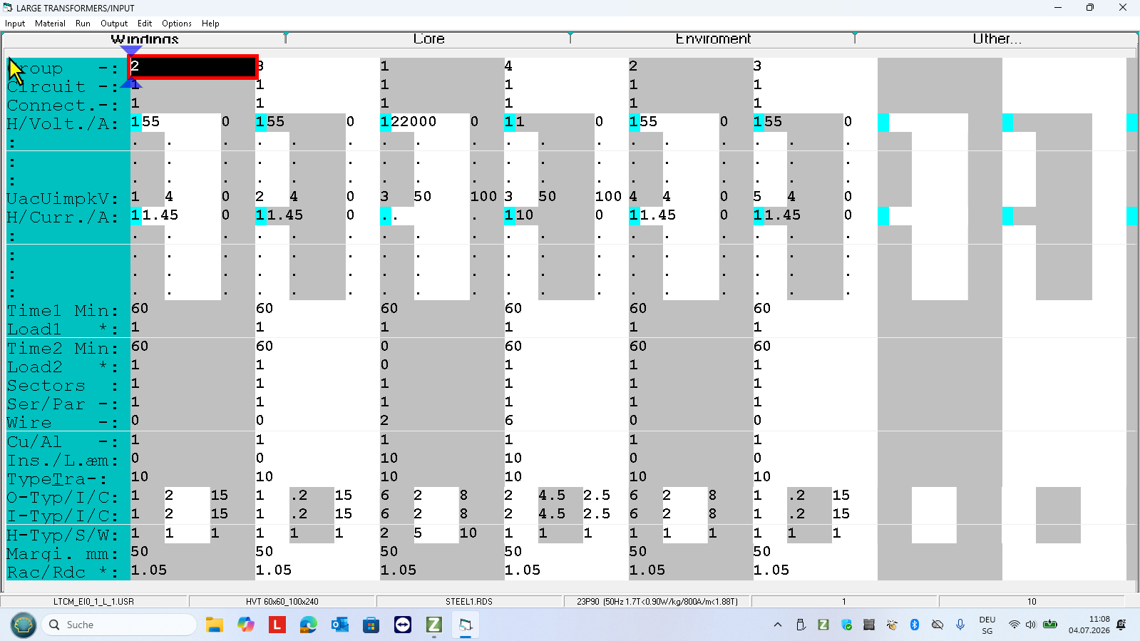
In this input screen are set the following parameter of all windings:
-The order of the windings:S1/2-S2/2-P-Screen-S1/2-S2/2
-The connection of windings S1 and S2
-Nominal voltages and currents
-50Hz, 1 min test voltages and BIL impulse test voltages
-Cu round wires for the windings and foil for the screen
-Spacing: If you double click the input fields O-Type or I-Typeand Margin, the program will automatically , according to the test voltages, recommend you the size of the gaps and the insulations.
In this case the space between the primary winding and screen is the oil gap of 2.5mm. The second version would be the pressboard tube of 5mm. With length of screen foil turn can be the capacitive current calibrated!
Core and steel
The core and the steel are set in the shown input file:
Steel : GO 23P90
C-Core : EE 320×300/60mm,
2 windows 100x240mm,
leg 60×60,
yoke 30×60
Min. winding diameter; 85mm
Press F4 to run the program.
You are in the output screen
In the output screen you can view,.print and save all results of the design.
If you would like to modify BY HAND some calculated parameters of the transformer, press F8 to print all results and then press F5 to open the test mode of design.
Test Mode
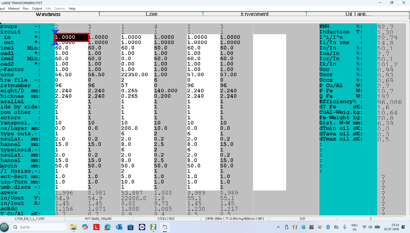
In the test mode you can modify by hand the following transformer parameters and press F6 to redesign:
-Turns
– Wire and foil size
– Material (Cu or Al)
Number parallel connected wires and their order in strand
– Cooling channels and insulations
– Margin
– Steel
and redesign the transformer by changing:
– input voltage
– load
– duty cycle of each winding
-frequency
-ambient temperature .
The phase delay of the output voltage in nominal operation at Uccx=0.69% is smaller than 30 minutes
-Primary S1 S2
V V V
22000 110.2 110
11000 55.2 55.2
2200 11.1 11.1
Output
For more informations about the design results open the file.