Designing 200kVA, Three Phase Transformer, 400V/400V, 50Hz, DY with Indirect Water Cooling
(=> Existing users – get your InputFile here)
Before reading this design example, please open the following link :
https://www.rale.ch/indirect_water_cooled_3_phase_inverter_choke.php and read some information about the main properties of an indirect water cooling.
Let’s show you first the positions of the coolers in the windings:
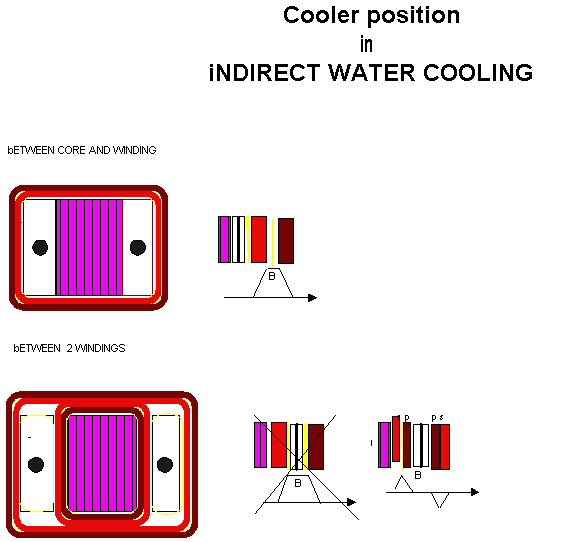
The indirect eater cooling is normally used on the cores with rectangular cross section and low voltage winding (<1000V). The core stack and leg width are approximately equal. The cooler is made by aluminum block with the one pipe. The cooler dimensions are:
-Width = leg width
-Height = core window hight
-Thickness = 15 to 30mm
The coolers are set in front and back of the stack, between 2 windings, where the leaking induction is very low (view picture above)
The number of coolers per transformer are:
-Single phase EI : N =2
-Single phase UI : N = 4
– Three phase RI : n = 6
The maximal allowed water temperature is 55°C.
The maximal allowed water speed through the piped is 1.5 m/s.
The water temperature rise dTW per cooler is calculated as follows:
WTmax = WTmin + 0.5*N*dTW
where:
-WTmax = maximale water trmperature
-WTmin = ambient temperature or smaller
-dWR = water temperature rise per cooler ,2… 5°K
At the ambient temperature 40°C and N=6 max. allowed water temperature rise has to be <= 3.5°k.
In order to create maximal thermal conductivity between the windings and the cooling water use:
– vacuum impregnation
– thin isolation with high thermal conductivity
– no air gaps.
Let’s now talk about the input:
Input
Windings
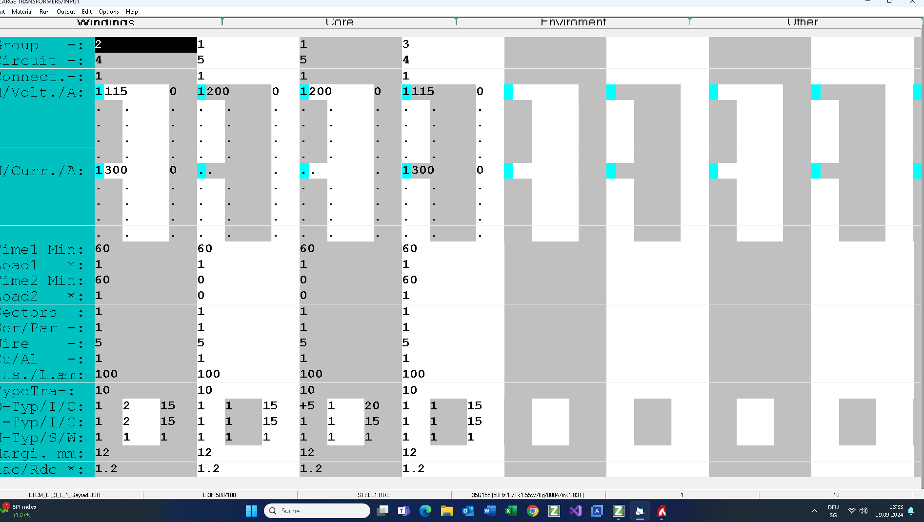
There are 4 windings per leg. The windings order is:
50% secondary 1 + 50% primary 1 + 50% primary 2 + 50% secondary 2.
In front and back of the core stack, between the primary 1 and the primary 2 I are placed 2 coolers per leg (O_Type = +5). The cooler thickness is 20mm. The thickness of the insulation of the coolers is 1mm.
Core
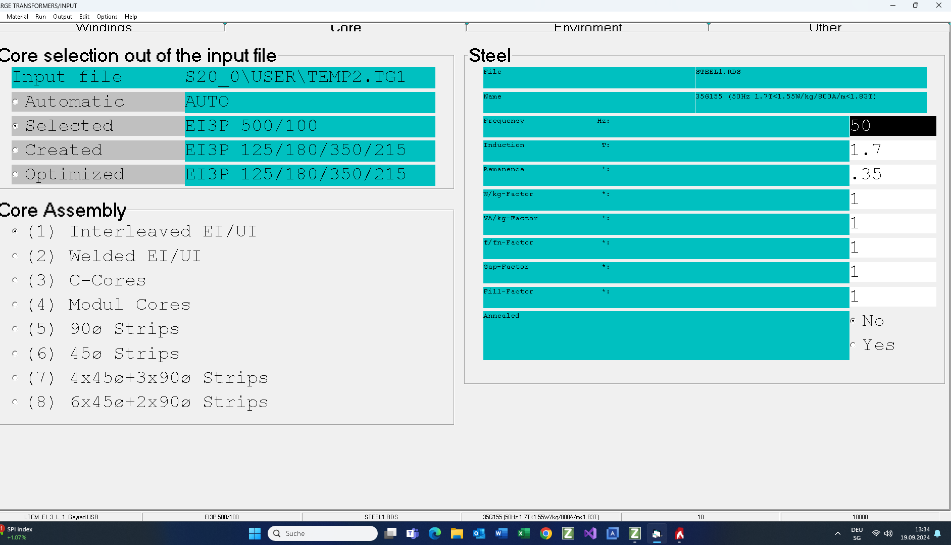
Note that a water cooled transformer has bigger windings losses than core losses. The resistive short circuit voltage is normally over 5% and the inrush current is no criterion of setting the induction.
Environment
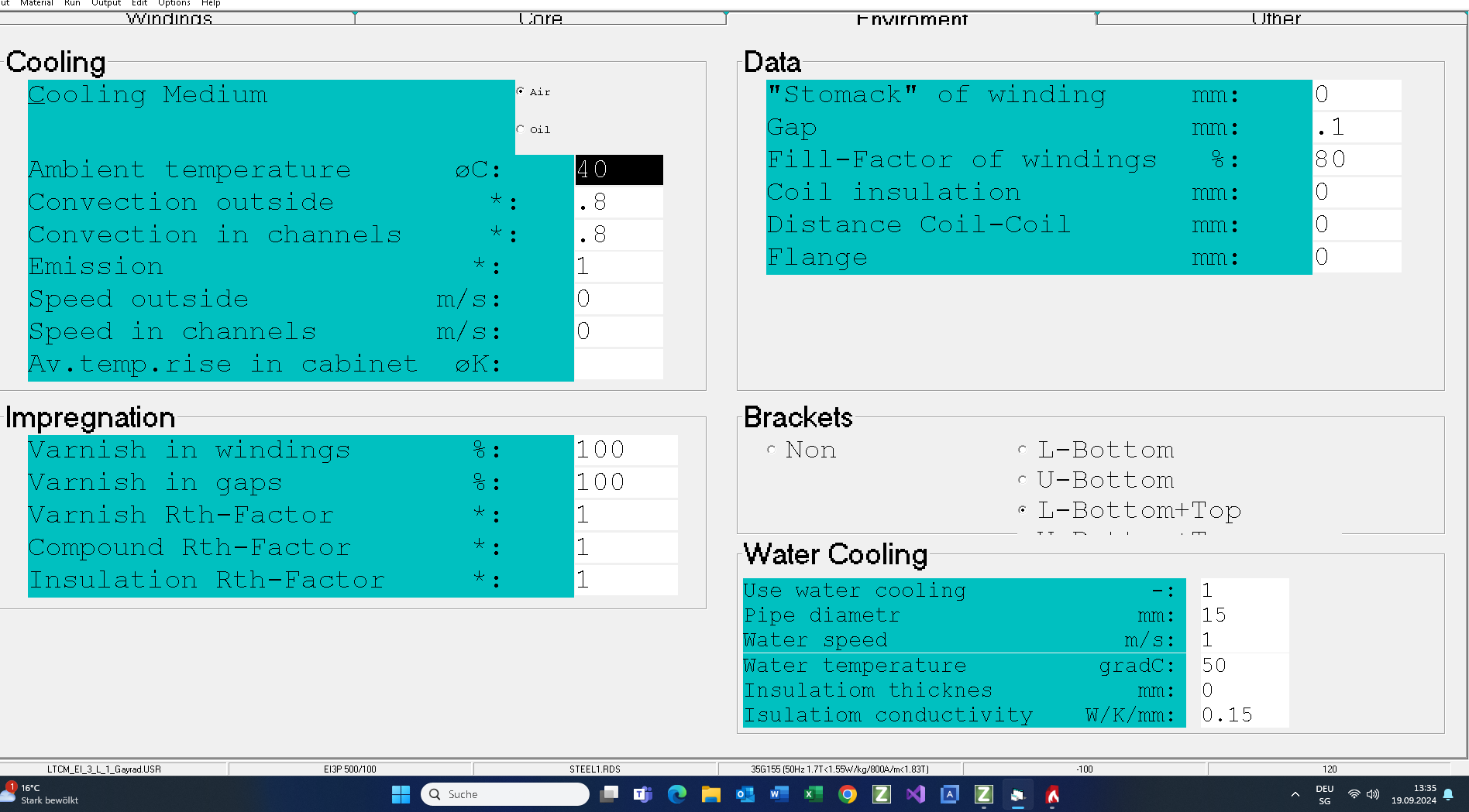
The typical settings for a water cooling are:
– Stomach = 0
– No air in the windings
– Thermal conductivity of the varnish and the isolation is 0.004W/°k/mm
The cooler settings:
– Pipe diameter = 15mm
– Water speed = 1m/s (max. allowed 1.5m/s)
– Max. water temperature = 50°C
Criterion
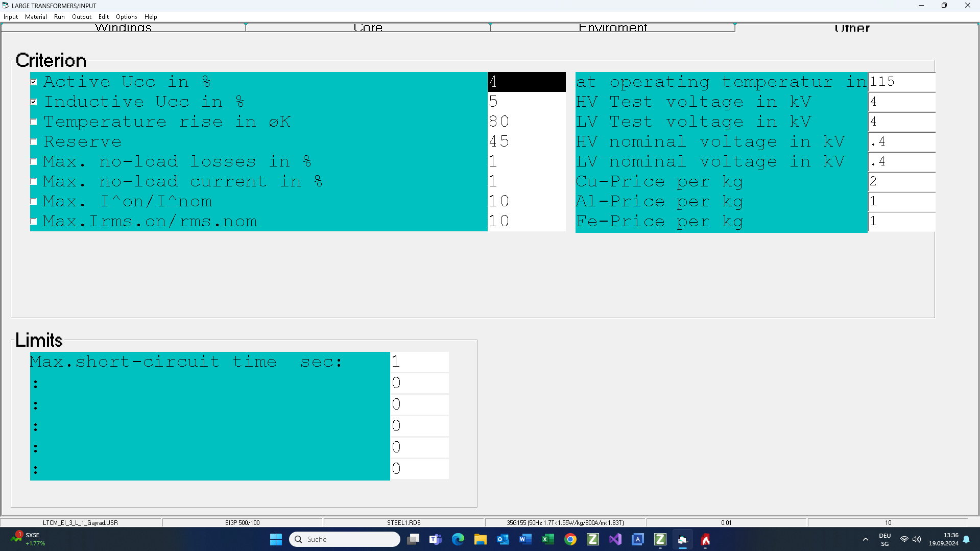
The typical design criterion of a water cooled transformer are winding losses (not temperature rise). Here is set Uccactive = 4% of the output power = 8kW
Output
Test
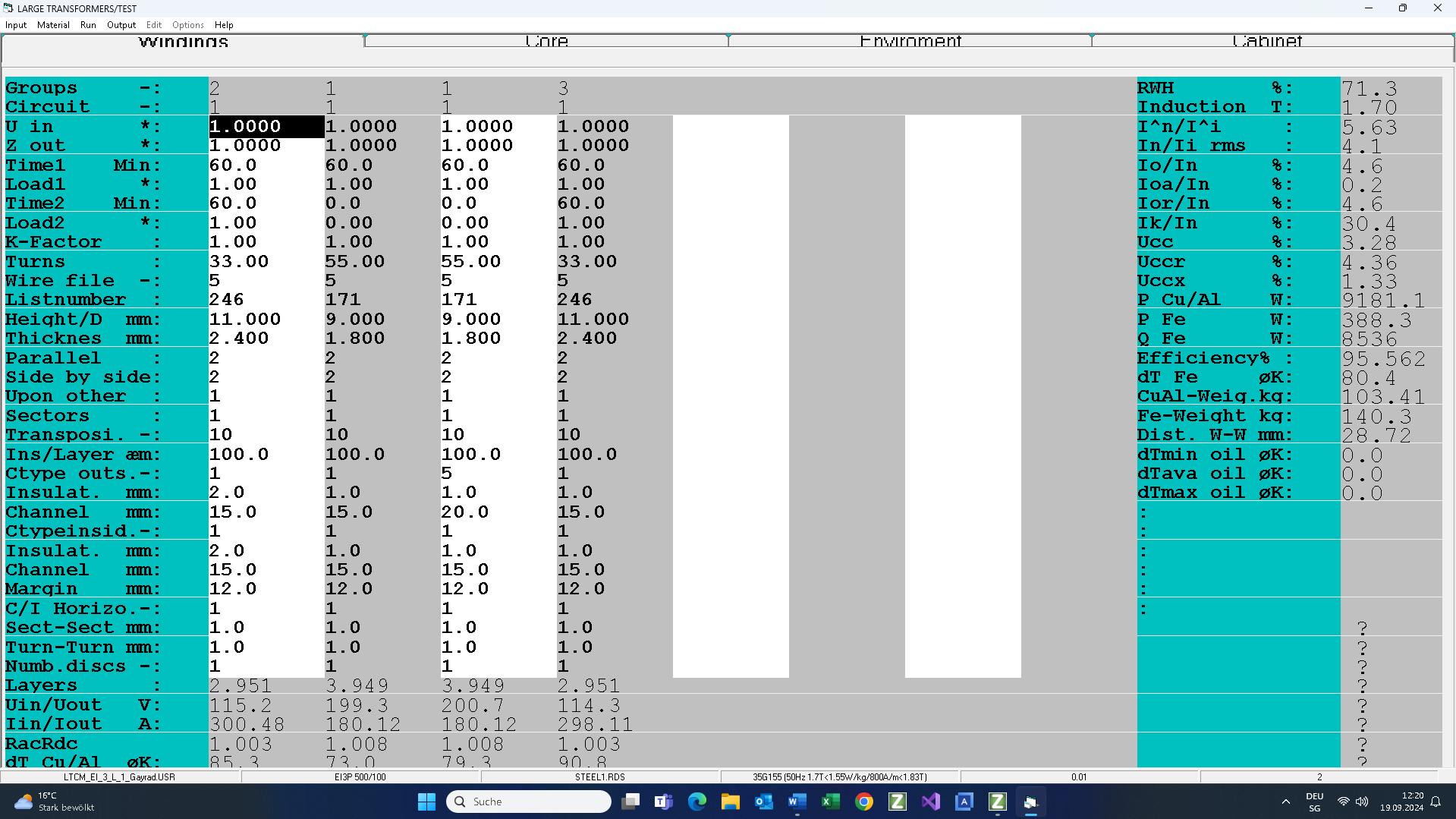
In the test mode you can modify tall calculated transformer parameters by hand and recalculate the transformer:
View the final results in the file: Output.
About the cooler:
– Cooling power : 1361W- Cooler temperature rise: 33°K
– Temperature of the cooler surface: 83°C
– Water temperature rise: 1.84°K
– Max. water temperature: 47.5°C
– Water pressure drop per cooler : 14 milliBar
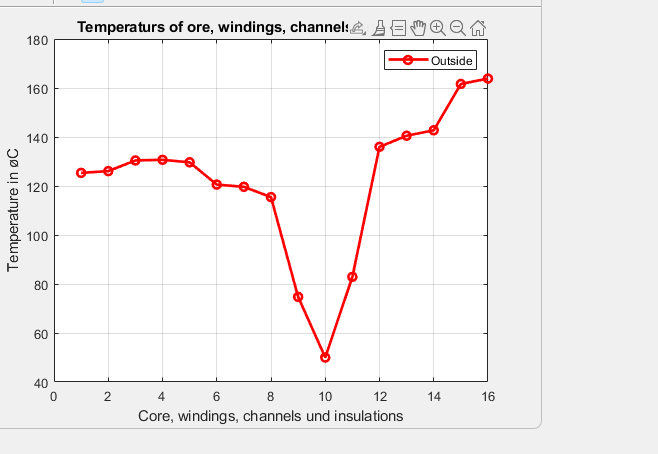
The following picture shows the temperatures in the winding on the side where the cooler is set
Legend:
-10 = water temperature
– 9,11 = cooler surface temperature
