CLICK HERE TO GET INPUT FILE: RaleInput_015
How to design a 50kHz, 240W
resonance transformer for an LLC converter
Typical application schemas of a resonance transformer
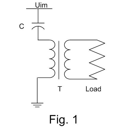
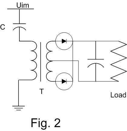
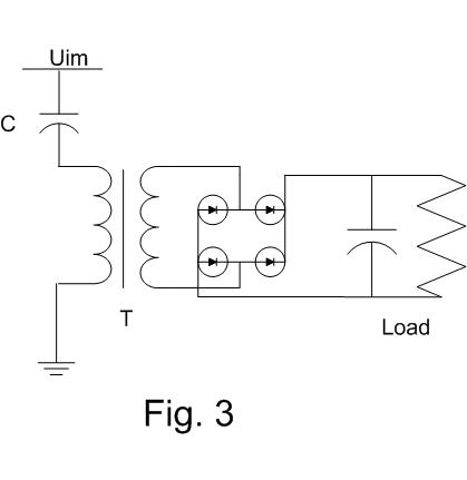
3 typical application schemas of the resonance transformers are shown in the pictures Fig 1, Fig 2 and Fig 3.
In the Fig. 1 is shown an AC-AC converter with the resonance transformer.
The Fig. 2 shows an AC-DC converter for very low DC-output voltage.
The most used AC-DC converter with the resonance transformer is shown in the Fig. 3.
The input voltage Uin is normally created by PWM . The capacitor C and the main inductance Lt of the resonance transformer T are in the resonance at first harmonic of the input voltage Uin.
The output current is “impressed”. Its value depends only on the value of the input voltage Uin and the capacitor C. Due to this fact, in the application with more secondary windings, the current distribution depends only on the load impedance and can not be controlled.
Electrical schema and design parameters
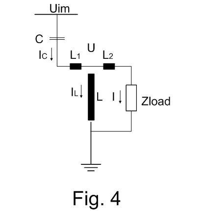
In the Fig. 4 are all relevant electrical parameters of a schema with the resonance transformers. Due to the fact that the leaking inductance L1 can be included into the impedance Xc and the inductance L2 into the load impedance Z the Electrical schema can be simplified to the schema in the Fig. 5.
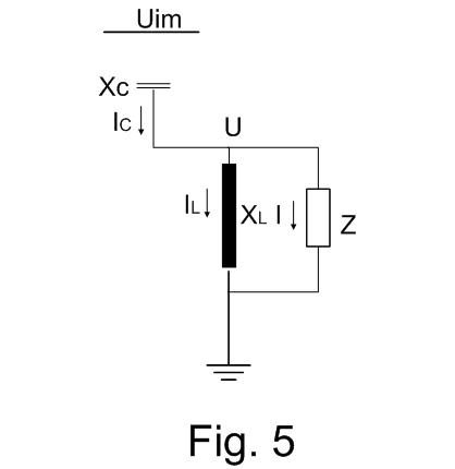
The parameters in the Fig. 5 are calculated as follows:
ω = 2πf
Xc = L1ω – 1/Cω
XL =jLω
Ż = Żload + jL2ω
where f is the main frequency of the input voltage Uin.
Note , if L1 is not big enough to be in resonance with the capacitor C at a frequency between the 3. and 5. voltage harmonic then an additional choke has to be used.
Using the first harmonic of the input voltage Uin1 you can calculate:
Uin1 jXL/(jXL – jXc)= I (Ż – jXL jXc/(jXL – jXc))
In the resonance operation mode of the capacitor C and the main transformer inductance L (Xc = XL) the load current depends only on the input voltage U1n and the capacitor C: It does not depend on the load impedance. The output current is constantis (impressed in the resonance operation mose ONLY. Note that the resonance would be broken in core saturation.
I = j Uin1/ Xc
and
Ů = jUin1 Ż/Xc
In a resonance transformer the magnetizing current is much higher than in a “normal” transformer and the material investment in the primary winding must be higher than in the secondary winding. Due to this fact it is recommended to wind the primary winding “outside”, over the secondary winding.
The main inductance L is normally prescribed and it has to be calibrated using gapped core.
The primary magnetizing current IL can be calculated as follows:
Uin1 Ż/(Ż – jXc)= IL (jXL -ŻjXc/(Ż – jXc))
For the resonance condition Xc = XL The value for the primary magnetizing current is:
IL = Uin1 Ż/Xc/XL and
IL = -jŮ/XL =- jŮ/Xc
So you can calculate the ratio between the primary magnetizing current and the primary load current:
IL/I = U/Uin1
Technical specifications of the 1200W resonance transformer
|
Schema Current I Xc = XL |
Fig. 3 Uin1/I =128 Ohm |
| Nominal output voltage Nominal output current Secondary voltage Secondary current |
24Vdc 10Adc 25Vac 9Aac |
|
Ambient temperature |
40°C 60°K |
Finally here are the inputs and the results of the resonance transformer:
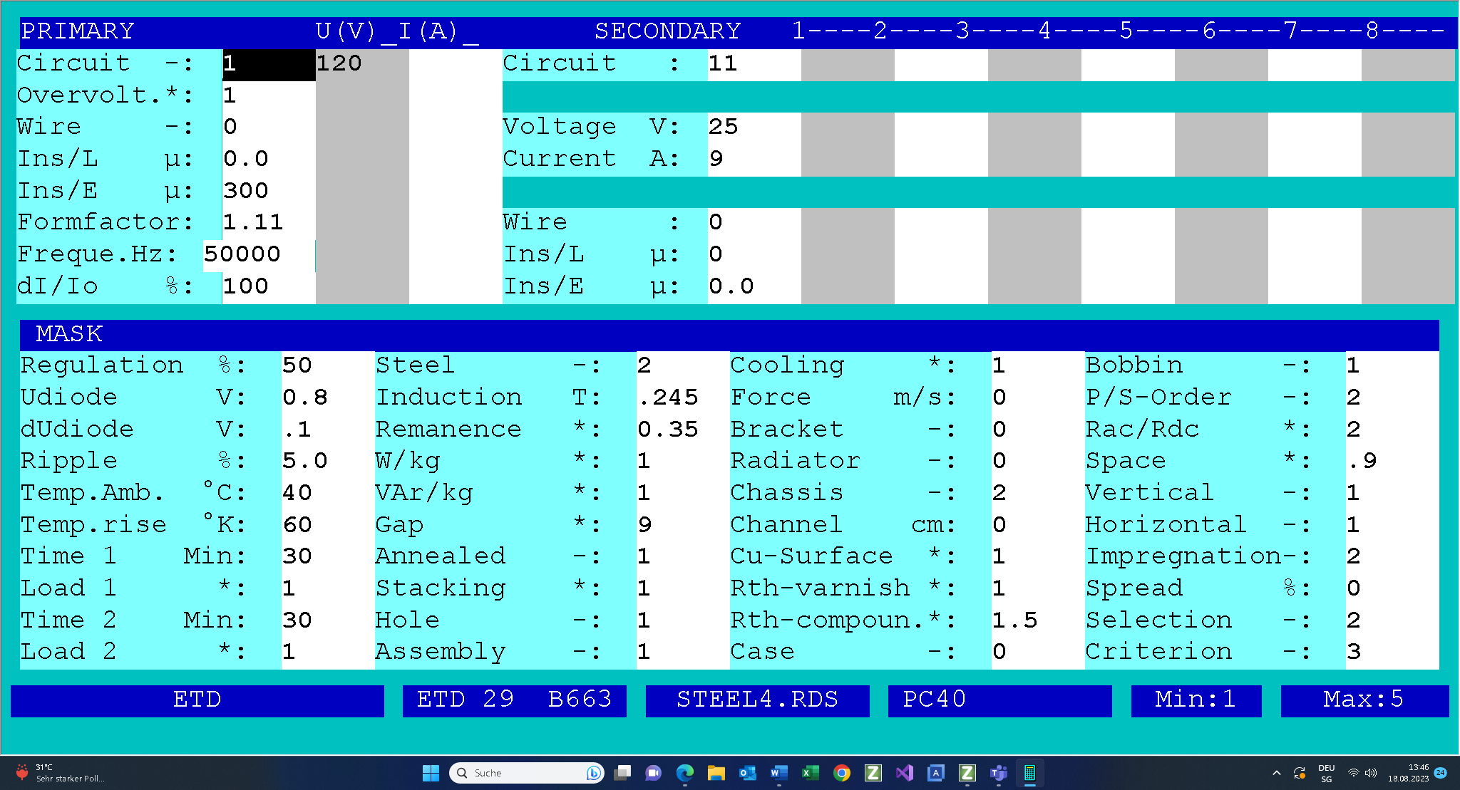
To obtain the results and to print them click on the following link.
Once again, the output current of the resonance transformers is “impressed”. It has approximately the sine wave form. The rectifier with the RC load is a non-linear load. Therefore the secondary voltage (and the primary voltage, too) has the rectangular voltage form.
The secondary circuit 11 or 31 is a good simulation of this operation mode with rectangular secondary voltage and the sine wave current.
Due to the fact that you can not prescribe the main inductance you have to manipulate the size of the gaps in the core in order to get the prescribed transformer main inductance XL = 128 Ohms . Gap = 9 means that you will need to sat all 3 gaps in the ETD core at
approx. 9 x 0.025mm = 0.225mm. Note that the gaps must be calibrated in order to get the prescribed main inductance .
With PS-Order = 2 primary winding is wound over the secondary winding because the ampere-turns of the primary windings are ca. 15% bigger.
In order to limit the number of the parallel connected round wires the eddy-current factor RacRdc is set to 2.