Creating a 4 lines 3 phases net in
a 3 lines 3 phases net using a Zn-transformer – about the operation mode of a Zn-transformer and its design
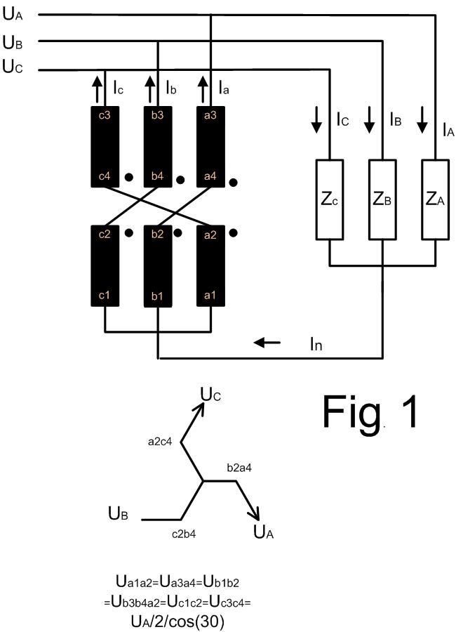
Typical application schemas of a Zn-transformer is shown in the Fig.1. The Zn-transformer has 6 equal windings which are connected in zig – zag.
If the 3 phase load is symmetrical (linear load complex impedances ZA = ZB = ZC ) then the there is no current in the neutral line ( In = 0 ) and the Zn-transformer runs in the no-load operation mode.

Typical application schemas of a Zn-transformer are shown in the Fig.1. The Zn-transformer has 6 equal windings which are connected in zig – zag.
If the 3 phase load is symmetrical (linear load complex impedances ZA = ZB = ZC ) then the there is no current in the neutral line ( In = 0 ) and the Zn-transformer runs in the no-load operation mode.
If the 3 phase load is symmetric (ZA = ZB = ZC) but non-linear (typical for some rectifier) then the currents IA, IB and IC can have the following form:
IA = I1m sin(ωt) +I3m sin(3ωt)+I5m sin(5ωt) +I7m sin(7ωt) +I9m sin(9ωt)+…
IB = I1m sin(ωt+120°) +I3m sin(3ωt) +I5m sin(5ωt+120°)+I7m sin(7ωt+120°) +I9m sin(9ωt)+…
IC = I1m sin(ωt+2400°) +I3m sin(3ωt)+I5m sin(5ωt+240°)+I7m sin(7ωt+2400°)+I9m sin(9ωt)+…
and the current in the neutral line is:
in = iA + iB + iC = 3 *I3m sin(3ωt) + 3*I9m sin(9ωt) + …
where I3m and I9m are max. values of the 3. and 9. current harmonics.
For this operation mode the curents through the Zn-transformer are:
Ia = ib = ic = in/3 = I3m sin(3ωt) + I9m sin(0ωt) + …
Note that the Zn-transformer works in this operation mode as a very powerful filter of the 3rd, 9th, … current harmonics.
Assume the rms values of the 3rd and 9th harmonic in all 3 phases of a 3x400V, 50Hz, three phase net are:
I3rms=33A
I9rms = 10A
then:
UA= UB = UC = 230 and the zig & zag voltage is 230/2/cos(30°) = 133V
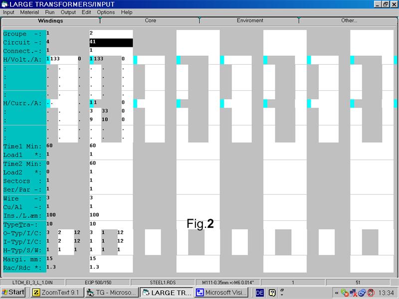
Run the Large Transformer Program and set the input as follows in the Fig.2:

Important remarks:
• Due to the fact that the transformer is driven by 50Hz you have to set a small 50Hz current.
• In order to set the 3. and 9. current harmonics you have to set Circuit = 41
• Do not forget to encrease the eddy current factor RacRdc.
• Note that the turns of the zig and zag windings have to be equal.
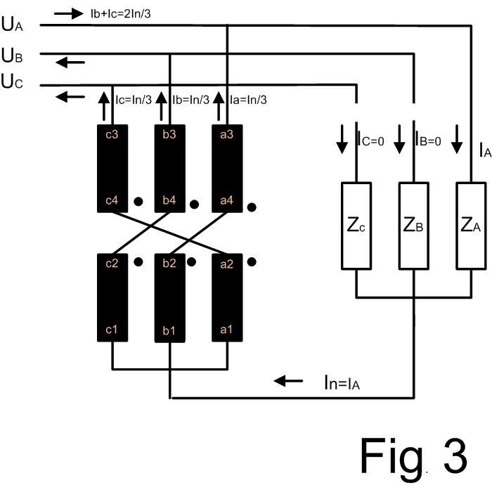
Normally the worst case for the Zn-transformer is unsymmetrical operation mode when only one phase is on load:

iA = I1m sin(ωt) + I3m sin(3ωt)+I5m sin(5ωt) + I7m sin(7ωt) + I9m sin(9ωt) +…
iB = 0
iC = 0
and the current in the neutral line is:
in = iA = I1m sin(ωt) + I3m sin(3ωt) + I9m sin(9ωt) + …
For this operation mode the currents through the Zn-transformer are:
Ia = ib = ic = in/3 = (I1m/3) sin(ωt) + (I3m/3) sin(3ωt)+(I5m/3) sin(5ωt) + (I7m/3) sin(7ωt) …
Assume the rms values of the current harmonics in the phase A in a 3x400V, 50Hz net are:
I1rms=90A
I3rms=33A
I5rms = 21A
I7rms=15A
then:
UA= UB = UC = 230 and the zig-zag voltage is 230/2/cos(30°) = 133V
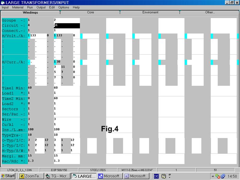
Run the Large Transformer Program and set the input as follows in the Fig. 4:

Finally note that you can use the Small Transformers Program if there are no current harmonics:
iA = I1m sin(ωt)