CLICK HERE TO GET INPUT FILE: RaleInput_105
Designing a 1600kVA/35kV, 50Hz Distribution Oil Transformer with oil tank
General Information: Technical Parameters
| Input voltage | 3 x 35000/20230V, star sine wave |
| Test voltage | 85kV, 50Hz, 1 min |
| BIL | 120 KV |
| Transformer output voltage | 3 x 690/400V, star |
| Line output current | 3 x 1340A, continuous operating mode |
| Frequency | 50Hz |
| Average oil temperature | 45°C |
| Max. temperature rise and/or max. Cu-winding losses at 75°C |
45°K at min.oil temperature rise 15°K
18000W => 1.125% |
| Short-circuit voltage | 7% |
| Ambient temperature | 25°C |
| Max. core losses | <3200W =< 0.2% |
| Max. no-load current | <1.3% |
| Test Voltage at 50Hz, 1 minute |
Primary 85kV, outside |
| Steel & Core Assembly | M5, annealed, strips for alternated stacking (4×45°+3×90° per shape), “round” cross section with 8 steps |
| Core Size | Optimized for minimal material price for: Cu_Price/Fe_Price = 2 with Cu-winding |
Creating Input
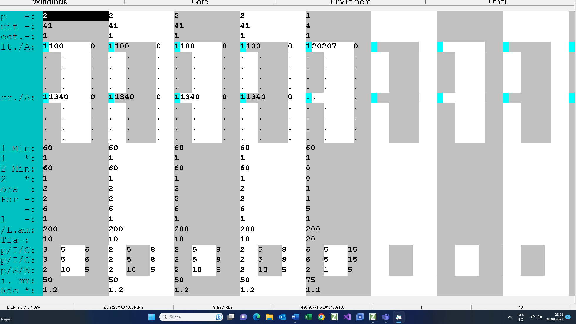
4 input screens are used to set the input parameters for designing a transformer:
• Winding parameters per limb
• Core
• Environment
• Other
and 3 screens for selection and set up of material :
• wires
• steels
• cores.
Criteria and Parameters of Design
The design of a distribution transformer is always framed by 5 criteria which have to be put into effect simultaneously:
• Short circuit voltage, 7%
• Winding losses at 75 °C < 18000W
• Winding temperature rise
• Core losses < 3200W
• No-load output current < 1.3%
Under this condition the first step is the optimizing the core size to match the above mentioned prescribed design criteria for the optimal material price using some additional parameters such as:
- Transformer cooling media is oil and oil tank cooling media is air: ONAN
- The secondary winding is inside.
- The setting of the voltages and currents normally is no problem.
- The next step is the space organization around the windings and the type of windings.
- The criteria are cooling, test & BIL voltages, short circuit voltage and existing company technology.
- In this design the secondary winding is made with Cu-foil and the primary winding with discs.
Windings parameters per leg
Secondary
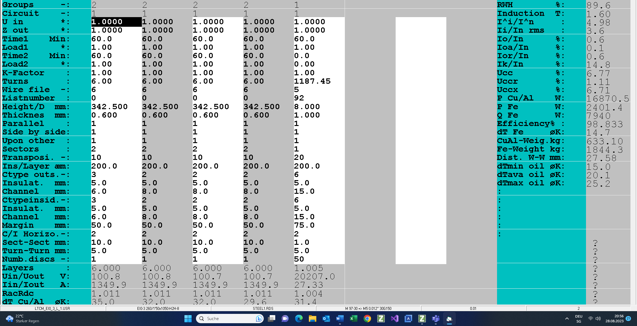
The secondary is created in star connection. The sine wave output voltage is 400V. It has 4 in series connected windings. Each winding has 2 parallel connected sectors.
The rms output current is 1336Arms.
There are no current harmonics and there is no duty cycle operation mode.
The secondary windings will be manufactured with Cu-foil with vertical cooling channels of 8mm and 15mm (due to bar welded connector).
The foil turns are insulated with 0.1mm isulation.
The margin to yoke is 50mm; 25mm less than the primary winding in order to suppress the eddy current losses in the foil windings!
Primary
The primary is created in star connection. The sine wave input voltage is 20230V.
There are no voltage harmonics and there is no duty cycle operation mode.
The primary will be manufactured with Cu-flat wire in disc winding technology with the horizontal cooling channel of h=5mm. The advantage of the disc windings is low voltage per turn without any partial discharging problems. In order to suppress the high BIL pulse voltage the wire is insulated with 0.15mm (0.3mm between 2 wires in a disc).

Core
On this input screen you can:
• select and manipulate the selected steel M97, 030mm (M5l)
• set the operating induction (1.6T) and the frequency (50Hz)
• select the core assembly 7 (45°&90°)
• and prescribe the core selection out of an input file. This option will not be used because the core size has to be optimized.
Environment
The cooling medium is oil with the average temperature 55°C. The cooling surface of the core is increased by using 4 L-brackets on the core. The minimum distance between the primary windings of 2 phases is 30mm. There is no flange but both windings have to be fixed in order to suppress the axial forces during the short circuit operation mode.
There is no air in the transformer and in the oil tank!
In order to get an optimal oil tank size, set (if possible) the min. oil temperature rise so high that the average oil temperature lies between 65°C and 75°C.
Other…
The selected criteria of the design and core optimization are the winding losses (18000W => 1.125%) at 75 °C and the inductive short-circuit voltage 6.4%. If you prescribe also the temperature rise then the program has to use the criterion which is more critical: either the winding losses or the temperature rise with the prescribed short circuit voltage.
The core losses and the no-load input current can be manipulated only with steel quality, core assembly and induction.
Core optimization
After you have set all input screens you need to select a core family and a core as template: 3 phase core family with 8 steps “round” cross section.
Click Core and then Optimize.
In this design Core diameter was 260mm.
Click Create and set X-Width=1150 and Y-Height = 1050mm
Change the core name to EI0-3 260/1150×1050 H2H 8
Click OK to close the optimizing procedure.
Test Mode
If you are not satisfied with the solution made by the program you can switch into the Test Mode and change your transformer by hand:
• Turns
• Wire and foil size
• Material (Cu or Al)
• Number parallel connected wires and their order in strand
• Cooling channels and insulations
• Margin
• Steel
• Technology parameter (impregnation, gaps,…)
and then you can set it under an operation mode changing:
• Input voltage
• Frequency
• Loads and their K-factors
• Duty cycle of each winding
• Ambient temperature
• Air flow

Output
Finally here are 4 printed pages showing the design results, to see them click on this link.
Nominal operating mode
On this output pages you can check the prescribed parameter:
• winding losses at 75 °C :17396W<18000W
• short voltage:7.09% (instead of 7%)
• core losses:2482W < 3200W
• No-load current : 0.64% < 1.3%
• Max temperature rise :36.7 °K
• Max. radial tension in short-circuit: 5 < 60 N/mm^2
• Max. temp. rises during 4s in short-circuit:77°K
• Max. pulse voltage distribution between 2 first primary turns < 750V
(Cp/Cs <3.5)
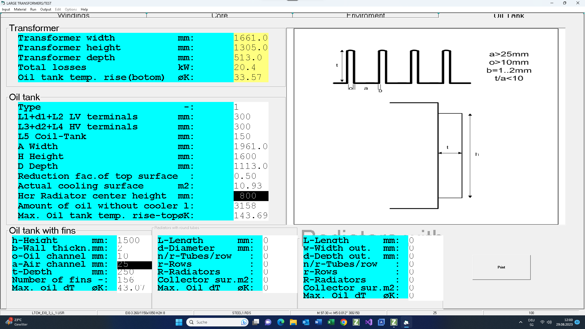
Oil tank Design

In this oil tank design the average oil temperature rise could be 43°K instead 33°K. If you would like to use this oil tank you need to redesign this transformer with min. oil temperature rise 25°K instead 15°K, or you increase the cooling ribs on the oil tank.