GET YOUR INPUT FILE BY CLICKING HERE: RaleInput_302
Designing Motor Filter Choke
About Motor Filter Choke
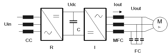
Fig.1 illustrates the main circuit diagram of a three-phase motor drive. The 3-phase mains Uin supplies the controlled rectifier R through the 3-phase commutation choke CC. The DC voltage Udc is regulated by the rectifier and smoothed with the capacitor C. The 3-phase AC voltage Uout is produced at the inverter outputs. The amplitude, frequency and form of this 3-phase AC voltage are regulated with the inverter and rectifier.
The typical form of the inverter output voltage per phase is illustrated in Fig.2.
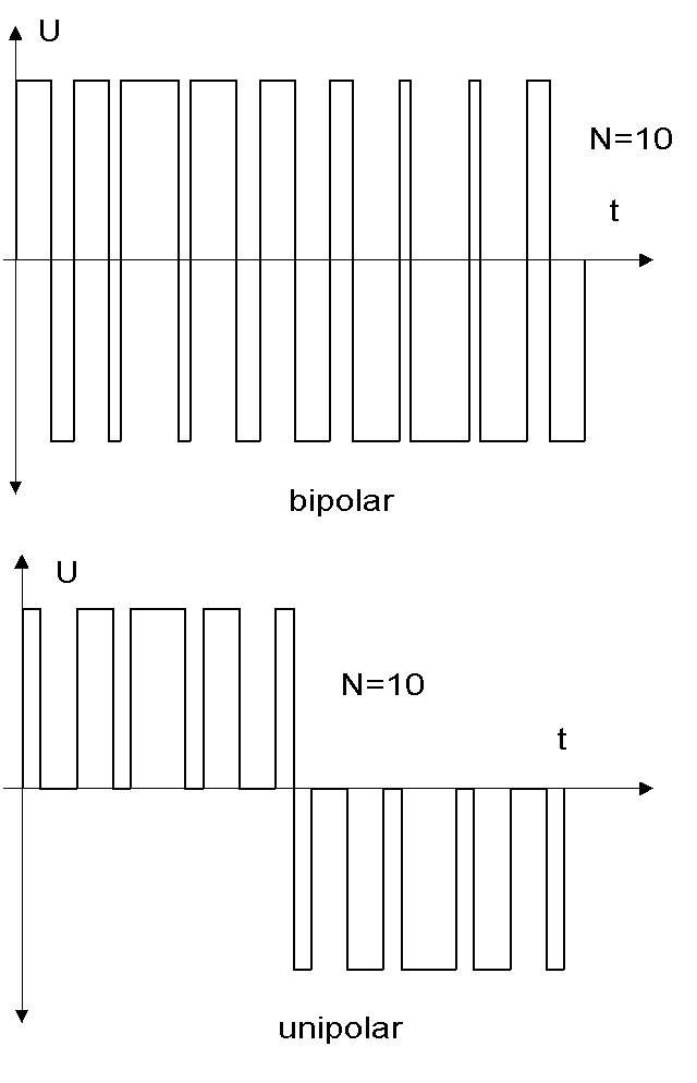
At an inverter modulation frequency N*f, the output voltage Uout essentially consists of three components:
• Fundamental frequency U with the frequency f (50Hz or 60Hz
• First harmonic U1=(0.45 – 0.90)*U with the fequency (N-1)**f.
Second harmonic U2=(0.45 – 0.90)*U with the frequency (N+1)*f.
Accordingly, the current through the motor filter choke Iout essentially comprises of 3 components:
• Fundamental frequency I with the frequency f. This current is “impressed” and its amplitude depends on the motor power.
• First harmonic I1 with the frequency (N-1) * f. The amplitude of this current depends on the voltage U1, the modulation frequency N*f and the inductance L of the motor filter choke:
I1=U1/(2* ¶*f*(N-1)*L).
• Second harmonic I2 with the frequency (N+1) * f. The amplitude of this current depends on the voltage U2, the modulation frequency N*f and the inductance L of the motor filter choke:
I2=U2/(2* ¶*f*(N+1)*L)
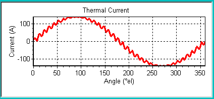
Fig.3 illustrates the current through a motor filter choke under the following conditions: I=100A, I1=I2=5A and N=36; Fig. 3:
Modulation frequency and inductance
The selection of the modulation frequency N*f plays a major role in interpreting the motor filter choke. 4-5 years ago, it was at approximately 2-3kHz. Today, modulation frequencies of 16kHz to 20kHz are used. For this reason, motor filter chokes are almost exclusively equipped with high quality steel or powder cores.
Selecting the optimum inductance L of the motor filter choke is a difficult task and depends on several parameters:
• Maximum voltage drop at the fundamental frequency
• Modulation frequency and fundamental frequency
• Steel
• Induction
• Efficiency
• Core material
• Price
An optimum solution can only be found with a close cooperation between the power electronics engineer and the manufacturer of the motor filter choke. Normally, the short-circuit voltage Ucc=100*(2* ¶*f)*L*I/U of the motor filter choke for the modulation frequencies between 2kHz and 20kHz lies between 4% and 8%.
Powder cores and their modular operation
Motor filter chokes are calculated below with the Rale Design System for the modulation frequency of 20kHz. After careful examination, we ascertained that the optimum solution today could be made only with high flux density powder cores from Micrometals, USA.
The reasons for selecting this company are as follows:
• It has an excellent technical documentation.
• It manufactures a range of single-phase EE-Cores (E305, E450 and E610) with the appropriate bobbins (the typical model of the powder core is toroidal core).
The special features and results of this decision are set as follows:
• The three-phase motor filter is made with 3 single-phase chokes.
• In order to cover higher powers several chokes must be connected in parallel.
• The value and linearity of the short-circuit voltage of all parallel connected chokes must be equal. Thus, the current distribution and the thermal load of the chokes connected in parallel proportional to the core power of the individual chokes is ensured.
• At an operating temperature over 75 ºC, special attention must be paid to the thermal aging. Under circumstances, an “old” powder core can have higher losses than before its first operation. Because of this, a powder core choke must be equipped with a thermal fuse. This is recommended in particular when using the powder cores from companies that provide no information regarding the thermal aging and/or where the modulation frequency is over 10kHz.
Design Example with Rale Design System
The three-phase motor filter is made with 3 single-phase chokes. The single-phase choke is to be calculated with the following parameters:
• Motor voltage = 3x400V, 230V per Phase
• Fundamental frequency = 50Hz
• Modulation frequency =20kHz
• Three-phase motor power = 34.5kVA
Phase current =34500/3/230=50A
• Short-circuit voltage Ucc=5%
Inductance L= (Ucc/100)*U/(2* ¶*f)/I=0.05*230/314/50=0.732mH
• The short-circuit voltage Ucc was selected in such a way, that the harmonics I1 and I2 remain less than 5% of the motor current I. Thus, the motor filter could be implemented without the capacitors FC (see Fig.1).
• Harmonic I1=U1/(2* ¶*N*f)/L=0.9*230/414/N/0.000732=2.25A, 19050Hz, angle 0°
Harmonic I2=I1, 20050Hz, abgle 180°
The harmonics I1 and I2 are increased by 10%. This compensates the influence of the harmonics that were not considered: I1=I2=2.5A.
We took into consideration the bipolar form of the inverter output voltage when applying the amplitude U1=U2=0.9*U (Fig.2).
• Ambient temperature = 40 ºC, natural cooling
• Temperature rise =75ºK
The choke is manufactured in the insulation class F. For protection, the choke must be provided with a thermal fuse for the response temperature at 150ºC.
• Powder core E610-26 from Micrometals. The gaps are implemented between two E-parts.
• Winding with Cu-foil with layer insulation of 0.05mm, vacuum-impregnated.
All above mentioned parameters are taken into consideration in the following Rale Design System input mask for calculating the chokes.
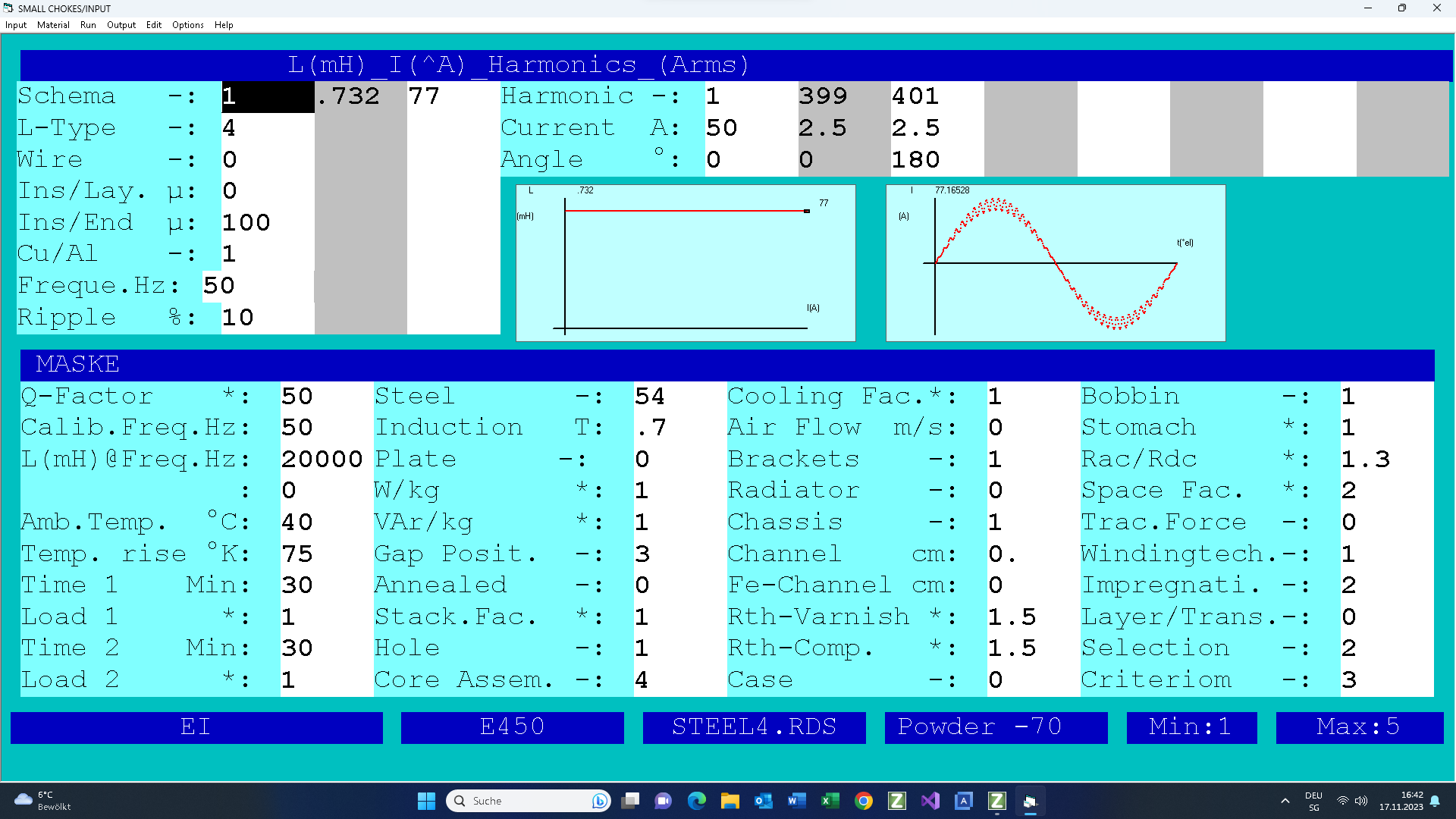
The two graphs above depict the inductance vs. current and the form of the thermal current.
The results of the design with these input screen above was in the test mode modified by hand:
1. The number of turns were rounded from 29.7 to 30.
2. The gap size from 09,1mm was set to 0mm! There is no need to calibrate the choke inductance.
3. In order to get full number of the layers the calculated wire of the diameter 4mm was exchanged by the 4,25 mm wire.
4. Fe losses ((15w) are smaller than Cu losses (27W)).
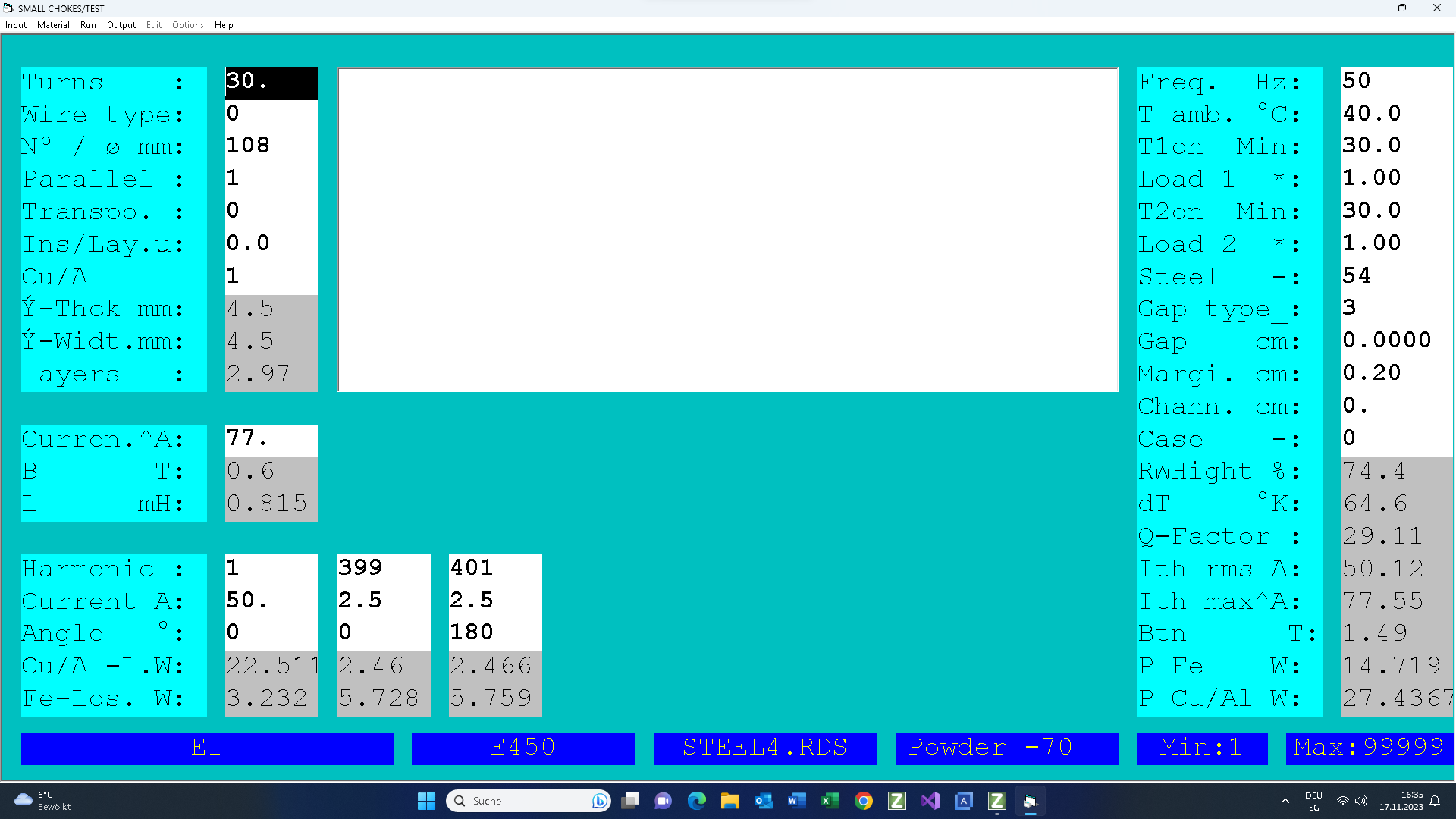
The calculation results can be accessed via the following link.
The minimum, average and maximum inductions in the core are shown to the right of the equivalent circuits. The induction Bx and By are responsible for generating the eddy current losses in the winding. It must be mentioned here that the magnetic fields was calculated with the help of numerical methods.
The core losses and the induction of each current harmonic as well as the core temperature are important for assessing the thermal aging of a powder core.