CLICK HERE TO GET INPUT FILE: RaleInput_306
Designing 3 Phase LC-Filter For Power Factor Correction,
50kVAr, parallel to Rectifier Bridge
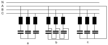
In the following picture are 3 typical schemas of the LC resonance filters. The most used is the schema a. The schema b uses the capacitors with higher nominal voltage. If the LC filter current has 3. And 9. Harmonic then you need to use the schema c with 3 single phase chokes.

The LC filter for power factor correction is always connected on the 3 phase,, 50Hz or 60Hz between the net and the load. The 50Hz or 60Hz current depends of the inductive power Q which has to be delievered:
I1 = Q/ph/U and Z1=U/I1
Where:
– Q => inductive power of the LC filter
– Pd => Number phases, normally ph=3
– U => For star connection: U=Ua=Ub=Uc; for delta connection: U=Uab=Uac=Ucb
Z1 = L*Omega-1/C/Omega- where Omega =2*pi*f, f=> net frequency, 50 or 60Hz.
Normally the resonance frequency for LC filter is 189Hz for the net frequency 50Hz or 227Ht for the net frequency 60Hz net. For these resonance frequency the ratio of the voltage Ul on the choke and Uc on the capacitor is ca.7%.
Ul/Uc= 0.07 at net frequency
Now you know Z1. You cn calculate C and L:
Xc = = 0.93*Z1 and C=1/Xc/Omega
Finally:
Xl = 0.07*Xc and L = Xl/Omega
Due to the fact that the non-linear load is the source of the current harmonics which flow from the load to the net and the LC-filter, the distribution of these harmonics between the net and the LC-filter depends on the net short circuit voltage and the inductance L in the LC filter. It means that the values of the current harmonics through the LC filter has to be prescribed by your customer.
Creating the input for the design of the choke:
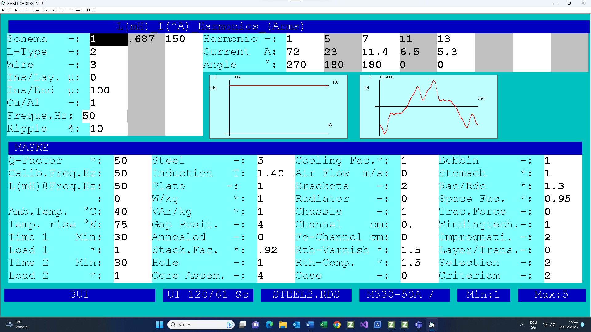
Schema: a
Q=50kVAr
Nrt 3 x 400/230V, short circuit voltage at 200A = 5%V
U=230V
f=50Hz
ph=3
I1=50000/3/230=72A
Z1=230/72=3.2 Ohm
Xc=0.93*3.2=3Ohm
Xl=0.07*3=0.21 Ohm
L=0.21/314=0.687 mH
Assume the load is 3 phase bridge rectifier with the line currents:
Ir1=200A, Ir5=36A, Ir7=22A, Ir11=14A and Ir13=12A
and
Zn5=5*0.05*230/72=.8 Ohm,Zn7=1.12,Zn11=1.76 amd Z13=2.08
and
Z5=5*Xl-Xc/5=0.45 Ohm, Z7=1.04,Z11=2.03 and Z13=2.5
Now you can calculate the 5. Current harmonic using :
Ir5=In5+I5 and
Z5*I5= Zn5*In5
or
I5=Ir5*(1+Z5/Zn5)
I5=23A, I7=11.4, I11=6.5 and I13=5.4
Note: If you want to use the schema b then you need to reduce tC or the factor 3 and to select the capacitor nominal voltage over 500V.
Input
• Set the inductance0.687mH at peak current (View the peak value on the current diagram on the input screen). The resonance frequency is 189Hz for Ul/Uc=7%
• Select the AC inductance: L-Type = 1
• Select Cu flat wire: Wire = 3
• The frequency of the first harmonic is 50Hz
• Set the rms values of harmonics of the thermal current. NormallyTtese harmonics need to be prescribed by your customer!
• Set the temperature rise 75°K and the ambient temperature 40°C
• Select grain oriented steel. Note that the induction will be optimized by program in order to get optimal relationship between core losses and winding losses,
• Set Gap = 4 and Core Assembly = 4 or better
• Select suitable 3 phase core family. If there are 3. and 9. harmonics (schema c) then you need to use 3 one phase cores.
• Use Al gap fixing platr: Plate=1
• Rac/Rdc=1.3

Test

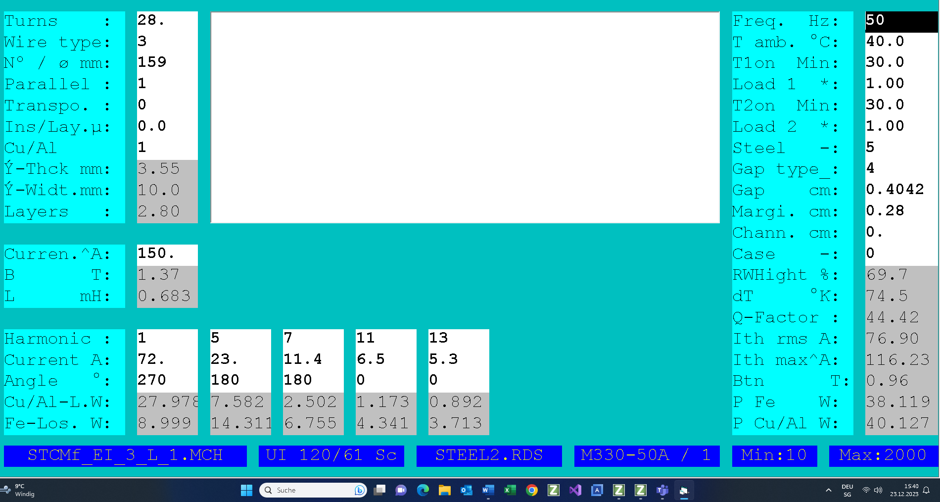
Output
Click here to get the results.