Designing a Constant Voltage Stabilizer 2000W, 1000V +-20%/11V+-1%,50Hz short circuit proof
This stabilizer has 2 magnetic components:
- Non-linear transformer
- Linear inductor with compensating winding
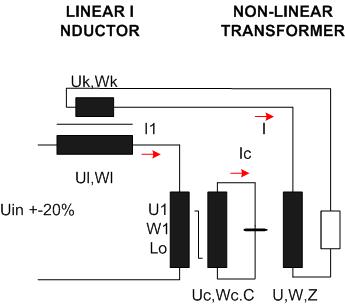
Basic settings for Constant Voltage Stabilizer
– Input voltage Uin = 1000V +-20%, 50Hz
– Output voltage 110V +-1%
– TDS factor < 15%, without L2&L5 filter
-Output power P =2000W, Powr factor =1
– Capacitor power Qc = 1.5*P = 3000Var
– Xl = Xc’ = Xc*U1^2/Uc^2
– Short circuit proof , isolation class F, Ambient temperature 40°C
– Efficiency > 96%
Basic settings for Non-Linear Transformer
- Core
– Name: EI 240/90
– Steel: 50A250, Annealed, high Si, low saturation, low noise, Hm=a*B^7
– Induction = 1,6425T . In order to get Q1 = Qc = 3000Var you have to calibrate the induction by adding or removing some laminations by hand. - Output winding
– Power P = 2000W
-Voltage U= 110V, +-1%, with compensation
– Current I = 18A
– I3 = (Wc/W)*Ic3/4.5 =2.6A
– I5 = (Wc/W)*Ic5/7.5=0.51A - Capacitor winding
– Power Qc = 3000Var
– Voltage Uc = 600V
– Current Ic1 = Qc/Uc = 5A
– Ic3 = Ic1*(3/5)* (3.5/4.5) =2.33A
– Ic5 = Ic1* (7.5/8.5)/5=0.88A
– Xc =600(5 =120 Ohm - Primary winding
– Voltage U1 = Uin/(1 + (P/Qc)^2)^0.5 =1000/1.2 =833V
– Current I1 = (P – j(Q1-Qc)/U1 = 2.5A un ferro-resonance
– I11 = Q1/U1 = Qc/U1 = 3.6A
– I13 = I11*3/5 =2.16
– I15 = I11/5=0.72
NON-LINEAR TRANSFORMER
1. Vector diagram, in ferro-resonance operating mode
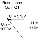
Note that the compensation voltage Uk has 90° phase delay to the voltage U1.
Xc’=Xl (CVT setting)
Wk = 0.09*(Wl*W/W1)*Xc’/Xl =11.7(12
Uk = Wk*Ul/Wl =12*570/969=7.05V
U1 = (833^2+7.05^2)^0.5 = 833.02=833V
2. Input
Use the input file by clicking on cvt.
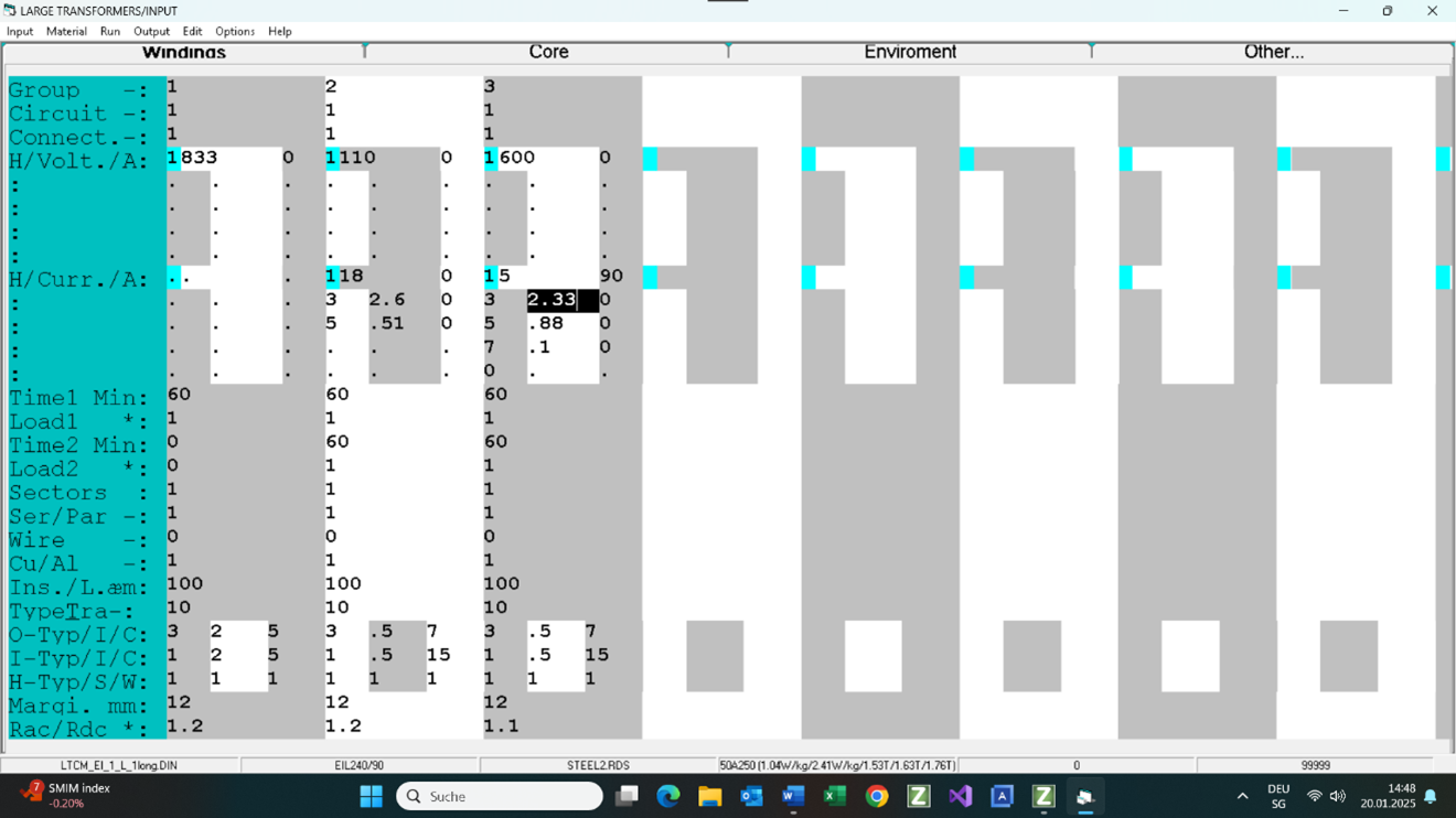
3. Output
Click here to get the output (PDF).
4. Temperature Rise
Note that the temperature rise in short circuit operation mode with I1 = 5A is < than 83°K
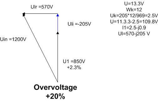
OVERVOLTAGE and COMPENSATION
1. The primary voltage setting in the test mode
The input voltage U1 is increased for 2%. The inductive primary current I1i = 0.9A and Uli = Xl*I2i ? 228*0.9 = 205V
If you do not like to use the compensation then the output voltage would be 11V +- 2.5%

LINEAR INDUCTOR Ll
- Core
– Name EI 240/30 with 3 gaps in the center lg
– Steel GO M165 = M6 - Input: Ll = 716mH; Peak current 7A at 1.4T
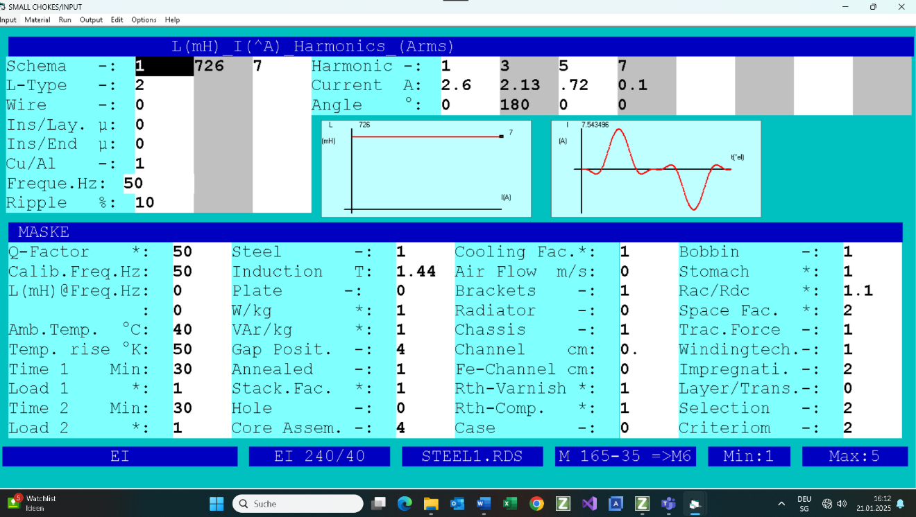
In the short circuit operating mode with 5A, 50Hz max temperature rise is <80°K.
L3&C3 qmd L5&C5 FILTERS
For TDH<5% of the output voltage you have to use the filter of in series connected L3&C3 and L5&C5on the capacitor winding:
Uc = 600V
C=26.5 microF
C3 +C5 = 0.91*C
C3=16 microF
C5 = 8 microF
L3=1/(9*C3*)mega^2)
L5=1/(25*C5*)mega^2)
Omega = 6.28*f, f => frequency
RECTANGULAR INPUT VOLTAGE
Your input voltage has the following form:
Uin(t) =( 4*Ua/pi)*(sin(O*t)+sin(3*U*t)/3+sin(5*O*t)/5+ …)
where:
-pi= 3.24
– O = 1*pi*f
– Ua max. value of the rectangular input voltage
In this design you have to use the first harmonic of the input rms voltage 4*Ua/pi/1.41
In the next step you have to calculate 3. and 5. current harmonics and add them to the calculated currents in the first stem